Rotating siphon type closestool

A toilet and siphon technology, applied in the field of sanitary ware, to achieve the effect of increasing pressure

Inactive Publication Date: 2015-09-16
TANGSHAN MONOPY CERAMIC
View PDF8 Cites 2 Cited by
  • Summary
  • Abstract
  • Description
  • Claims
  • Application Information

AI Technical Summary

Problems solved by technology

[0004] The present invention aims to solve the above-mentioned problems existing in the existing siphon toilet, and provides a ringless eye, which uses the joint action of the water guide groove and the ring

Method used


Image

  • Rotating siphon type closestool
  • Rotating siphon type closestool
  • Rotating siphon type closestool

Examples


Embodiment Construction

[0016] The present invention is described in detail below through examples, and the purpose is only to better understand the content of the present invention. Therefore, the examples given are not intended to limit the content of the present invention.

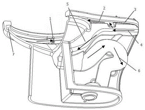
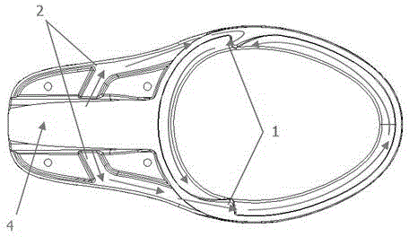
[0017] see figure 1 , figure 2 , the connection between the water tank and the toilet body is provided with a water inlet 3, the main waterway 4 connected to it is arranged below the water inlet 3, and the loop waterway 2 connected with it is respectively arranged on both sides of the main waterway 4, two loop waterways 2 Respectively extend to the annular concave water guide groove 7 provided on the inner edge of the upper mouth of the pot body. The terminal of one circle waterway 2 is provided with the circle surface spray hole 1 facing the front water guide groove 7, and the other end of the circle waterway 2 is provided with The spray holes 1 on the circle surface of the water guiding groove 7 at the rear, and the water...


PUM


Abstract

The invention relates to sanitary ware, in particular to a rotating siphon type closestool. The rotating siphon type closestool comprises a water inlet located in the joint of a water tank and a closestool body, a main water way located in the closestool body and connected with the water inlet, and a jetting water route connected with the main water way. Two ring way water routes connected with the main water way are arranged in the closestool body and arranged on the two sides of the main water way respectively, and extend to annular inwards-concave water guide grooves formed in the inner edge of an upper opening of a pot body respectively. A ring face jet hole facing the front water guide groove is formed in the tail end of one ring way water route, and a ring face jet hole facing the rear water guide groove is formed in the tail end of the other ring way water route. Water flow sprayed out of the ring face jet holes forms rotating water flow on the surface of a pot cavity. The rotating siphon type closestool is free of ring holes; through the combined action of the water guide grooves and the ring way water routes, the pressure can be increased in the flushing process, it is ensured that the water flow can rotate on the surface of the pot cavity, and the rotating pot body flushing effect is achieved.

Description

technical field [0001] The invention relates to a sanitary ware, in particular to a whirling siphon toilet. Background technique [0002] The traditional siphon toilet, after the water tank is flushed, relies on the gravity of the water flow and the suction effect formed by the siphon structure of the toilet itself to pump the dirt into the sewer to complete the flushing and sewage discharge process. The existing problems are: due to insufficient flushing pressure, the water flow is too scattered and not concentrated during flushing, and the flushing force is not enough, and it is difficult for the water flow to form a rotation on the surface of the pot body, leaving a dead corner for flushing, resulting in residues of dirt on the surface of the pot body, and scouring The toilet can't be completely flushed once, and needs to be flushed many times, resulting in a waste of water resources. [0003] CN201220191704 discloses a jet siphon toilet, which adds a jet auxiliary chann...

Claims


Application Information

Patent Timeline
IPC IPC(8): E03D11/08
Inventor 李树元马爱军寿志满佟双喜王瑞雪张刚孙仕良关义明郭金健吕艳茶王银环董珊珊
Owner TANGSHAN MONOPY CERAMIC
Why Eureka
Try Eureka