Chamfer lock floor production method

A production method and floor technology, applied in the direction of chemical instruments and methods, layered products, lamination devices, etc., can solve the problems that the substrate cannot be effectively protected, the chamfer width and angle are limited, and the service life of the floor is damaged. Achieving good hot pressing compounding effect, large chamfering angle and improving product quality

Active Publication Date: 2018-01-16
ZHEJIANG KINGDOM NEW MATERIAL GRP CO LTD
View PDF10 Cites 0 Cited by
  • Summary
  • Abstract
  • Description
  • Claims
  • Application Information

AI Technical Summary

Problems solved by technology

[0003] However, in the production of this type of locking floor on the market at present, the chamfering of the product is mostly carried out at the same time when the mortise is opened, and the chamfering tool needs to be used for chamfering, and only the wear-resistant layer above 0.5mm can be chamfered. The floor is chamfered, and the width and angle of the chamfer are limited by the thickness of the wear-resistant layer; when chamfering the wear-resistant layer with a lower thickness, it is easy to expose the base material, so that the edge of the floor is not wear-resistant, and the base material The material cannot be effectively protected, which greatly damages the service life of the floor

Method used


Image

  • Chamfer lock floor production method
  • Chamfer lock floor production method
  • Chamfer lock floor production method

Examples


Embodiment 1

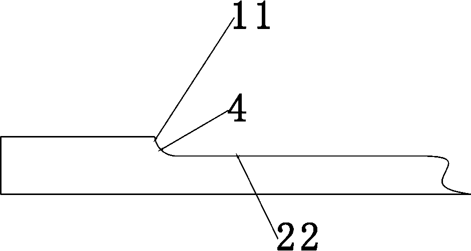
[0022] The wear-resistant layer 1, the color film layer 2, and the substrate layer 3 that make up the chamfered locking floor of the present invention are sequentially laid up, and 5 pairs of chamfering templates with a fillet radius of 0.4 mm are used for the arc chamfering 4 The laid-up floor is chamfered; the chamfering template is a shallow basin, and a radius of 0.4 is set between the first inner wall of the inner surface of the shallow basin and the second inner wall of the inner surface of the shallow basin. mm arc chamfering, the first inner wall 11 is the side wall of the shallow basin, and the second inner wall 22 is the bottom of the inner surface of the shallow basin; wherein, the temperature during hot pressing is 135°C (the positive and negative deviation is 5°C), the hot pressing time is 1800 seconds (plus or minus 20 seconds). When hot pressing, the floor will sink into the template by 1mm from top to bottom to form a completely closed shape. In order to solve t...

Embodiment 2

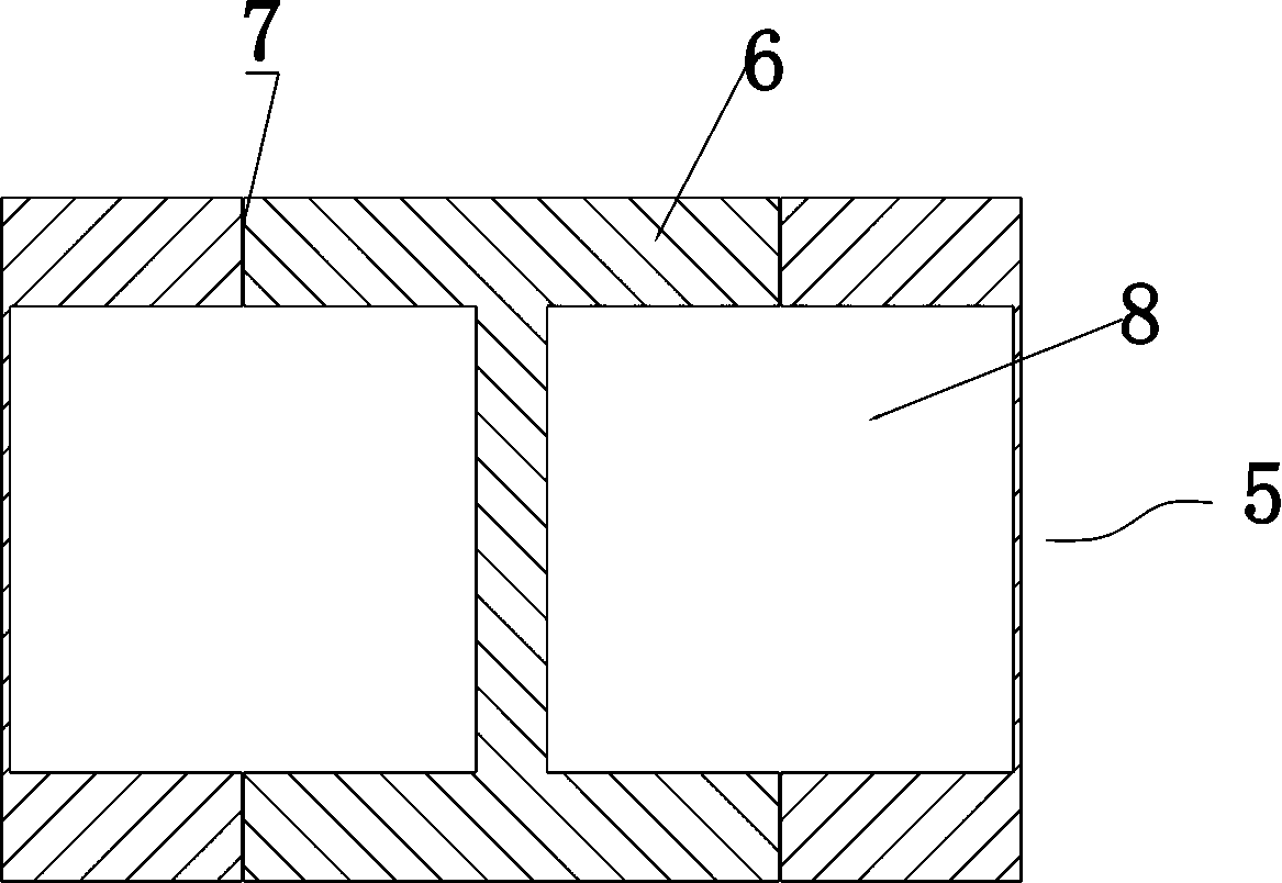
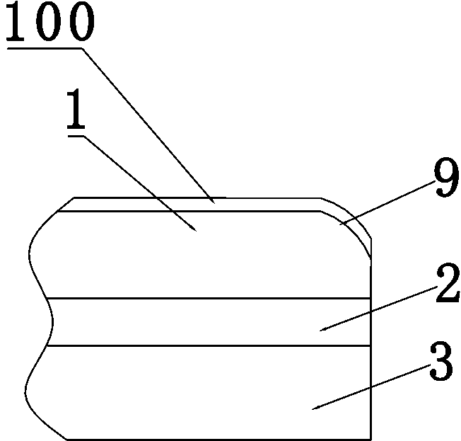
[0024] The wear-resistant layer 1, the color film layer 2, and the substrate layer 3 that make up the chamfered locking floor of the present invention are laid up in sequence, and a chamfering template with a rounded corner radius of 1 mm is used for arc chamfering (not marked) 5. Chamfer the laminated floor; among them, the temperature during hot pressing is 125°C (with a plus or minus deviation of 5°C), and the hot pressing time is 2000 seconds (with a plus or minus deviation of 20 seconds). , the floor will sink into the formwork by 1mm from top to bottom to form a completely closed shape. In order to solve the problem of exhaust in the formwork, four exhaust holes 7 are symmetrically arranged on the basin wall of the chamfered formwork. The air hole 7 of the vent hole has an inner diameter of 2mm; then, use a rubber roller with a hardness of HB 20° (with a plus or minus deviation of 2°) to UV-coat and cure the floor surface obtained above to obtain a UV film 100; finally T...


PUM

PropertyMeasurementUnit
radiusaaaaaaaaaa
hardnessaaaaaaaaaa

Abstract

The invention discloses a production method of a chamfered locking floor, which is characterized in that it comprises the following steps: a. laying up the layers that make up the floor in sequence; Chamfering under hot pressing; c. Using rubber rollers to UV coat and cure the surface of the floor obtained in step b; d. Grooving and tenoning the floor obtained in step c to obtain a finished product. Wherein, the edge of the chamfering template has circular arc chamfering, the present invention does not need a chamfering tool with high manufacturing cost, that is, it can realize a larger and wider chamfering angle of the lock floor with a thinner wear-resistant layer, Improved product quality.

Description

technical field [0001] The invention relates to the field of floor production, in particular to a production method for chamfered and locked floors whose chamfers are not limited by the thickness of the floor wear-resistant layer. Background technique [0002] In recent years, locking PVC plastic flooring has been widely used. It is easy to lay, waterproof and moisture-proof, easy to take care of, and has a long service life. It is especially suitable for laying in public places with large traffic such as shopping malls or commercial office buildings. [0003] However, in the production of this type of locking floor on the market at present, the chamfering of the product is mostly carried out at the same time when the mortise is opened, and the chamfering tool needs to be used for chamfering, and only the wear-resistant layer above 0.5mm can be chamfered. The floor is chamfered, and the width and angle of the chamfer are limited by the thickness of the wear-resistant layer; ...

Claims


Application Information

Patent Timeline
Patent Type & Authority Patents(China)
IPC IPC(8): E04F15/10B32B37/06B32B37/10B32B38/00
Inventor 戴会斌
Owner ZHEJIANG KINGDOM NEW MATERIAL GRP CO LTD
Why Eureka
Try Eureka