LED light source drive board

A technology of LED light source and driver board, which is applied in the field of lighting, can solve the problems of rising labor costs, low pass rate, cumbersome process, etc., and achieve the effects of facilitating automated production, improving production efficiency, and convenient assembly

Pending Publication Date: 2015-09-16
LEEDARSON IOT TECH INC
View PDF5 Cites 1 Cited by
  • Summary
  • Abstract
  • Description
  • Claims
  • Application Information

AI Technical Summary

Problems solved by technology

Generally, LED lighting products need to be driven to provide a stable power supply. The driver boards of existing LED lamps use manual plug-in wave soldering for larger devices. This production method is cumbersome and has a low pass rate, and wave soldering is h

Method used


Image

  • LED light source drive board

Examples


Example Embodiment

[0010] The present invention will be described in detail below through specific embodiments:

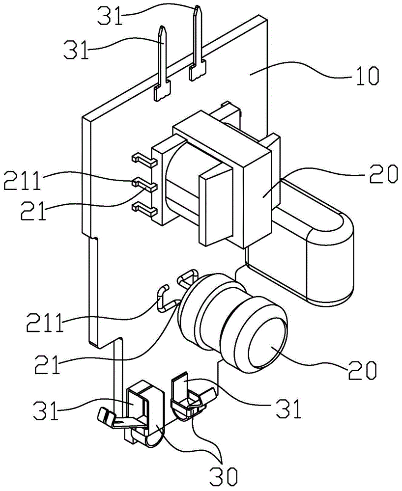
[0011] figure 1 It is a perspective view of the LED light source driving board of the first embodiment of the present invention. The LED light source driving board 10 is used to supply power to the LED light source board. At least one electronic component 20 is provided on one side of the LED light source driving board 10. At least one electrical connection terminal 30 is also provided on the board 10. Preferably, the electronic components 20 and the electrical connection terminals 30 are all arranged on one side of the LED light source driving board 10.

[0012] Please refer to figure 1 At least two electrode pins 21 are provided on these electronic components 20, and the ends of these electrode pins 21 are all bent to form a supporting section 211. All the supporting sections 211 of all the electrode pins 21 are located on a plane so that these The electronic components 20 can be pla...


PUM


Abstract

The invention relates to an LED light source drive board used for powering an LED light source board. One side of the LED light source drive board is provided with at least one electronic component; each electronic component is provided with at least two electrode pins; the tail ends of the electrode pins are bent into support segments; the support segments of the electrode pins are all located on a same plane so that the electronic components can be placed flat on the LED light source drive board; the electronic components are all welded to the LED light source drive board through the electrode pins. The LED light source drive board is simple in structure, convenient to assemble and convenient to automatically produce.

Description

Technical field [0001] The invention relates to the field of lighting, in particular to an LED light source drive board. Background technique [0002] In recent years, due to the rapid development of the LED industry, LED lamps have gradually replaced traditional lighting lamps. Generally, LED lighting products need to be driven to provide a stable power supply. The existing driving boards of LED lamps use artificial plug-in wave soldering for larger devices. This production method is cumbersome and the pass rate is low, and the wave soldering is harmful to the environment. The pollution is large, and the labor cost is increasing year by year. In the manual plug-in link, it is inevitable that workers neglect to insert the wrong parts, resulting in a low pass rate. Summary of the invention [0003] In view of this, it is necessary to provide an LED light source driver board with a simple structure, convenient assembly, and convenient automated production. [0004] The technical sol...

Claims


Application Information

Patent Timeline
IPC IPC(8): F21V17/10F21V21/002F21V23/00F21Y101/02
CPCF21V17/101F21V21/002F21V23/004
Inventor 陈小波庄佳卿刘宗金张翼
Owner LEEDARSON IOT TECH INC
Why Eureka
Try Eureka