
An Optimal Design Method for Composite Wave Plate Phase Retarder

A technology of phase retarder and composite wave plate, applied in instruments, optics, optical components, etc., can solve the problems that the maximum deviation of design parameters is not easy to control, the structural freedom is not very large, etc., and achieve the effect of large degree of freedom and convenient control.

Active Publication Date: 2017-03-29
WUHAN EOPTICS TECH CO LTD
View PDF6 Cites 0 Cited by
  • Summary
  • Abstract
  • Description
  • Claims
  • Application Information

AI Technical Summary

Problems solved by technology

In 1955, S.Pancharatnam (S.Pancharatnam, Proc.Indian.Acad.Sci.A, Vol.41, pp.137-144, 1955) proposed a new achromatic compound wave plate design method, which will Three wave plates of the same material are combined, among which, the middle wave plate is a half-wavelength wave plate, its optical axis forms a certain angle c with the two wave plates on both sides, and the two wave plates on both sides have the same phase Retardation δ, and the two wave plates are placed parallel to the optical axis, so that adjusting the size of c and δ can obtain achromatic composite wave plates of different bands, thus realizing the achromatic function of the same material composite wave plate, but The degree of freedom in the structure of this composite wave plate is not very large, and the maximum deviation of the design parameters within the designed band range is not easy to control

Method used


Image

  • An Optimal Design Method for Composite Wave Plate Phase Retarder
  • An Optimal Design Method for Composite Wave Plate Phase Retarder
  • An Optimal Design Method for Composite Wave Plate Phase Retarder

Examples


Embodiment Construction

[0037] In order to make the object, technical solution and advantages of the present invention clearer, the present invention will be further described in detail below in conjunction with the accompanying drawings and embodiments. It should be understood that the specific embodiments described here are only used to explain the present invention, not to limit the present invention. In addition, the technical features involved in the various embodiments of the present invention described below can be combined with each other as long as they do not constitute a conflict with each other.

[0038] In the present invention, the method for optimizing the design of the composite wave plate phase retarder can be implemented using the following process:

[0039] Step 1 Select the applicable band Γ for the composite wave plate phase retarder. According to the actual application of the designed composite wave plate phase retarder and its corresponding ellipsometry system, select the rang...


PUM


Abstract

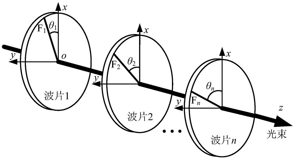
The present invention discloses a composite wave plate phase delayer optimal design method which comprises the following steps of (1) forming a composite wave plate phase delayer by n quarter zero order wave plates, (2) determining the change range of the central wavelength and optical axis azimuth of each quarter zero order wave plate, (3) obtaining the transmission Jones matrix of a kth quarter zero order wave plate, (4) obtaining the equivalent Jones matrix of the composite wave plate phase delayer, (5) obtaining the equivalent characteristic parameter of a composite wave plate, (6) obtaining the system matrix of an ellipsometer measurement system, (7) obtaining the system matrix condition number of the ellipsometer measurement system, (8) obtaining the maximum value of the ellipsometer measurement system in a wave band range Gamma, and (9) adjusting the central wavelength and optical axis azimuth of each quarter zero order wave plate, obtaining the maximum value of each adjustment, and then obtaining the minimum value in all maximum values. The method can be well adapted to the use need of the ellipsometer measurement system.

Description

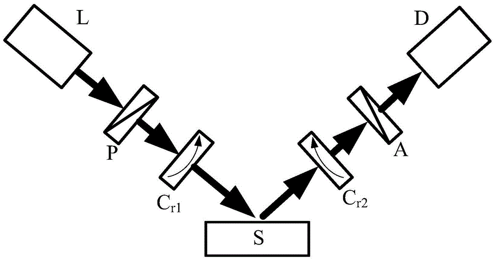
technical field [0001] The invention belongs to the technical field of optical phase retarders, and more specifically relates to an optimal design method for a composite wave plate phase retarder. Background technique [0002] Ellipsometry is an optical method to study the phenomena and characteristics of the interface or film between two media. Its principle is to use the polarization transformation that occurs when the polarized beam is reflected or transmitted on the interface or film, including phase difference and amplitude ratio. Ellipsometer (referred to as ellipsometer) is a general-purpose optical measuring instrument developed by using ellipsometry technology. The basic principle is to project special elliptically polarized light onto the surface of the sample to be measured through a polarizer, and measure the reflected light (or transmitted light) of the sample to obtain the polarization state change of the polarized light before and after reflection (or transmi...

Claims


Application Information

Patent Timeline
Patent Type & Authority Patents(China)
IPC IPC(8): G02B5/30
CPCG02B5/3083
Inventor 江浩刘世元谷洪刚张传维
Owner WUHAN EOPTICS TECH CO LTD
Learn More