Cutting tool

A technology of cutting tools and working heads, which is applied in the direction of manufacturing tools, metal sawing equipment, metal processing equipment, etc., can solve the problems of difficult lifting and heavy weight for users, and achieve the effect of smooth lifting

Active Publication Date: 2015-09-23
NANJING CHERVON IND
View PDF6 Cites 1 Cited by
  • Summary
  • Abstract
  • Description
  • Claims
  • Application Information

AI Technical Summary

Problems solved by technology

[0003] At the end of the specific cutting process, the user often needs to lift the cutting head, but generally speaking, the cutting head is heavy because of the integration of the motor and the transmission mechanism, and it is often difficult for the user to lift it.

Method used


Image

  • Cutting tool
  • Cutting tool
  • Cutting tool

Examples


Embodiment Construction

[0024] The following describes the present invention in detail with reference to the drawings and specific embodiments.

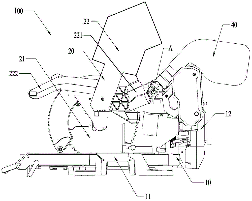
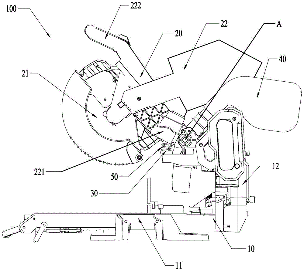
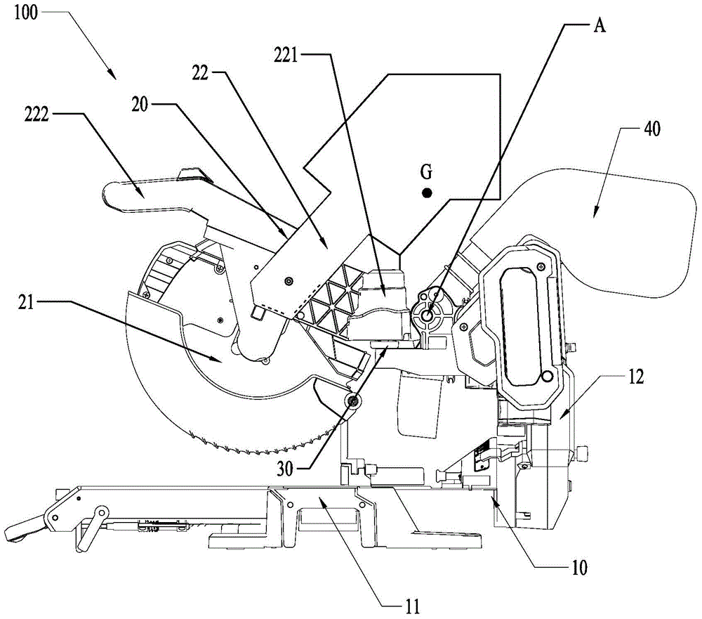
[0025] Reference Figure 1 to Figure 7 As shown, the cutting tool 100 of the present invention includes: a base assembly 10, a cutting head 20, and a bracket assembly assembly 30.

[0026] Wherein, the base assembly 10 includes a base 11 and a rotating bracket 12, and the rotating bracket 12 is arranged above the base 11. Specifically, the base 11 is used to place or position the object to be cut and to support the entire cutting tool 100, and the rotating bracket 12 may be provided on one side of the base 11, which is mainly used to connect the cutting head 20 and, for example, dust suction Component 40 and other structures. It should be noted that if the cutting tool 100 of the present invention is a miter saw, the rotating bracket 12 can form a rotating connection with the base 11 with an axis parallel to the saw blade 21 to realize the miter cutting functio...


PUM


Abstract

The invention discloses a cutting tool which comprises a base assembly and a cutting work head. The base assembly comprises a base and a rotating support, wherein the rotating support is arranged above the base. The cutting work head comprises a saw blade, a motor, a transmission mechanism and a head shell, wherein the motor and the transmission mechanism are arranged in the head shell and drive the saw blade so that the saw blade can achieve one or more of pivoting movement, linear reciprocating movement and curve reciprocating movement. The head shell and the rotating support are in hinged joint, the head shell comprises at least one power assistance sleeve with the opened bottom end and the sealed top end, and a spiral spring is arranged in the power assistance sleeve, wherein the top end of the spiral spring butts against the head shell, and the bottom end of the spiral spring butts against the rotating support. The cutting tool has the advantages that the spiral spring is adopted for assisting the cutting work head to be bounced, and a top end assembling part of the power assistance sleeve is arranged so that the top end of the spiral spring can be curved forwards and backwards respectively when the cutting work head is located at a downward pressing position and a lifting position to assist the operation of a user.

Description

Technical field [0001] The invention relates to a cutting tool, in particular to a cutting tool using a saw blade. Background technique [0002] For cutting tools, generally in order to realize the cutting depth can be adjusted, the cutting head is often connected to the base assembly by rotation, and the cutting depth of the saw blade is changed by turning during cutting. [0003] At the end of the specific cutting process, the user often needs to lift the cutting head, but generally speaking, the cutting head is relatively heavy due to the integrated motor and transmission mechanism, and it is often difficult for the user to lift it. Summary of the invention [0004] In order to solve the shortcomings of the prior art, the purpose of the present invention is to provide a cutting tool that can assist the user to conveniently lift the cutting head and not feel laborious when pressing it down. [0005] In order to achieve the above objectives, the present invention adopts the followi...

Claims


Application Information

Patent Timeline
Patent Type & Authority Applications(China)
IPC IPC(8): B23D47/02
Inventor 陈智丰朱坤
Owner NANJING CHERVON IND
Why Eureka
Try Eureka