
Device for supporting container for cryogenic media

A cryogenic medium and container technology, applied in the installation device of container structure, the geometry/arrangement/size of container structure, the method of container discharge, etc., can solve the problem of ineffective use of ships and achieve the effect of solid design scheme

Inactive Publication Date: 2011-08-17
TGE MARINE GAS ENG GMBH
View PDF9 Cites 1 Cited by
  • Summary
  • Abstract
  • Description
  • Claims
  • Application Information

AI Technical Summary

Problems solved by technology

However, the disadvantage of horizontal support is that it cannot effectively use the base provided by ships or stationary equipment

Method used


Image

  • Device for supporting container for cryogenic media
  • Device for supporting container for cryogenic media
  • Device for supporting container for cryogenic media

Examples


Embodiment Construction

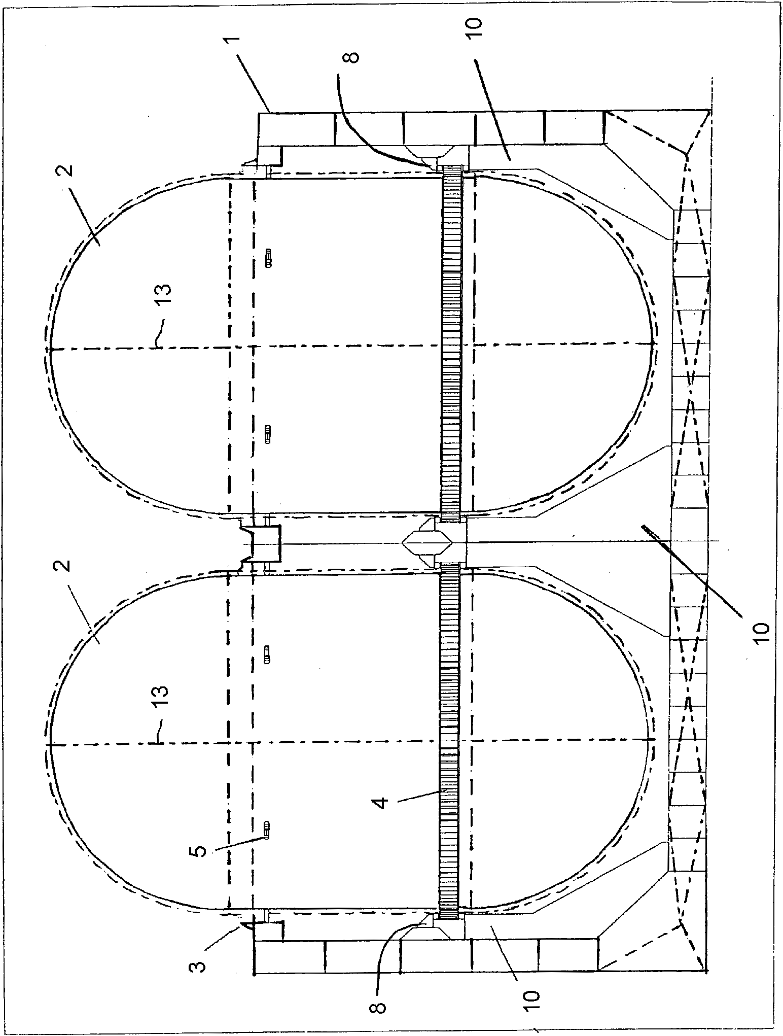
[0064] figure 1 A sectional view transverse to the longitudinal axis of the vessel 1 is shown. Two vertically placed containers 2 for LNG can be seen. A plurality of such arrangements are sequentially provided in the ship 1 along the length direction of the ship 1 .

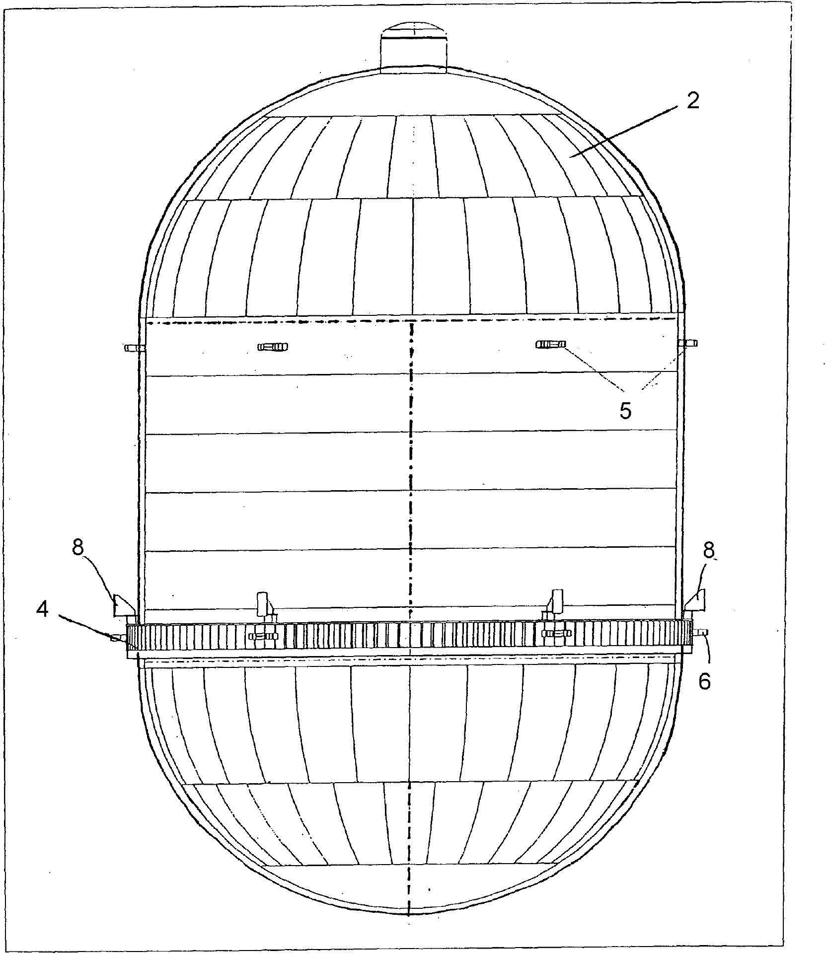
[0065] The container 2 is cylindrical about a longitudinal axis 13 and has an annular, radially protruding annular flange 4 in its lower half.

[0066] The annular flange 4 supports the respective container 2 via a base 10 annularly surrounding each container.

[0067] Above the ring flange, a cantilever frame 8 is fixedly connected to the vessel 1 , which limits the upward play of the ring flange 4 and thus prevents the vertical container 2 from being lifted.

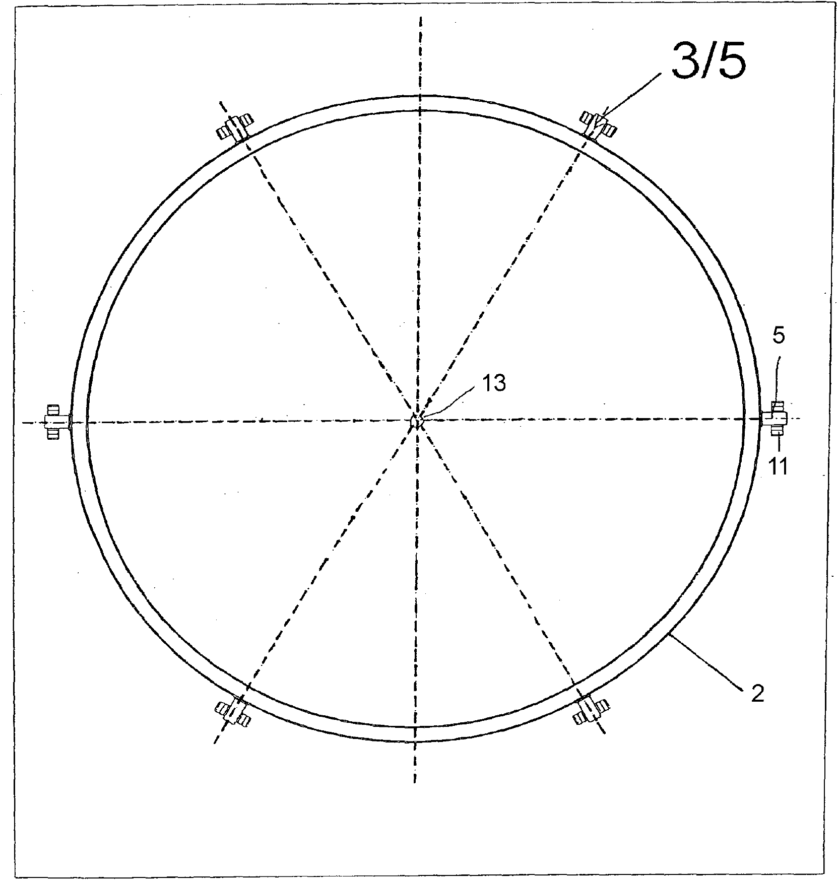
[0068] Furthermore, above the annular flange 4 a plug 5 protruding from the outer surface of the container is shown. In this case, six bolts 5 are used per container 2 , which are arranged circumferentially at the same height and at the same angular d...


PUM


Abstract

The invention relates to a device for supporting an independent container (2) for cryogenic media, particularly LNG, in a vertical position in a ship (1) or a stationary facility (1). The device comprises a support for the container (2), which supports the container (2) on a corresponding foundation (10) of the ship (1) or the facility (1) through a thermally insulating layer (7) and which enables a horizontal relative motion between the container (2) and the foundation (10).

Description

technical field [0001] The present invention relates to a device for supporting an independent, in particular cylindrical, container / tank (Tank) for a cryogenic medium, in particular liquefied natural gas (LNG), in a vertical position on a ship or In stationary equipment such as off-shore / offshore supports (Off-Shore-Lager) or in processing stations. Background technique [0002] Containers for cryogenic media, especially liquefied gases, and the structure for supporting them place high demands on the structural design due to the possibly considerable thermal movements that occur when filling and unloading the container . LNG has special requirements for this because it is cooler than most technical liquefied gases (e.g. ethylene loading temperature is around -100°C). [0003] In particular cylindrical containers are known, which can be essentially in the form of one cylinder or also in the form of two parallel cylinders intersecting each other; the latter are also known a...

Claims


Application Information

Patent Timeline
Patent Type & Authority Applications(China)
IPC IPC(8): F17C13/08
CPCF17C2223/0161F17C2260/011F17C2201/0109F17C2223/033F17C2205/018F17C2260/031F17C2205/0119F17C13/082F17C2221/033F17C2270/0105F17C13/081F17C2205/0134F17C2270/0118F17C2201/052F17C2205/0184F17C2201/032F17C3/02F17C13/08
Inventor F-T·阿佩尔S·格哈特L·本纳特
Owner TGE MARINE GAS ENG GMBH
Learn More