
Vibration disc type screw conveying device

A conveying device and vibrating plate technology, which is applied in metal processing, metal processing equipment, manufacturing tools, etc., can solve problems such as low efficiency and high labor intensity, and achieve the effects of high accuracy rate, labor saving, and error correction rate improvement

Inactive Publication Date: 2015-09-23
TIANJIN DONGMING ELECTRONICS IND
View PDF8 Cites 2 Cited by
  • Summary
  • Abstract
  • Description
  • Claims
  • Application Information

AI Technical Summary

Problems solved by technology

[0002] In the prior art, the installation of heat-adjustable screws on semi-finished circuit breaker shells usually includes two modes: manual screw placement and machine screw delivery, and manual screw placement is inefficient and labor-intensive; machine screw placement is usually conveyed by a vibrating plate, and vibration The forward and reverse directions of the nails conveyed by the disc may be inconsistent, so how to design a vibrating disc screw conveying device that realizes the consistent front and reverse of the screws transported to the designated place has become a research topic for those skilled in the art

Method used


Image

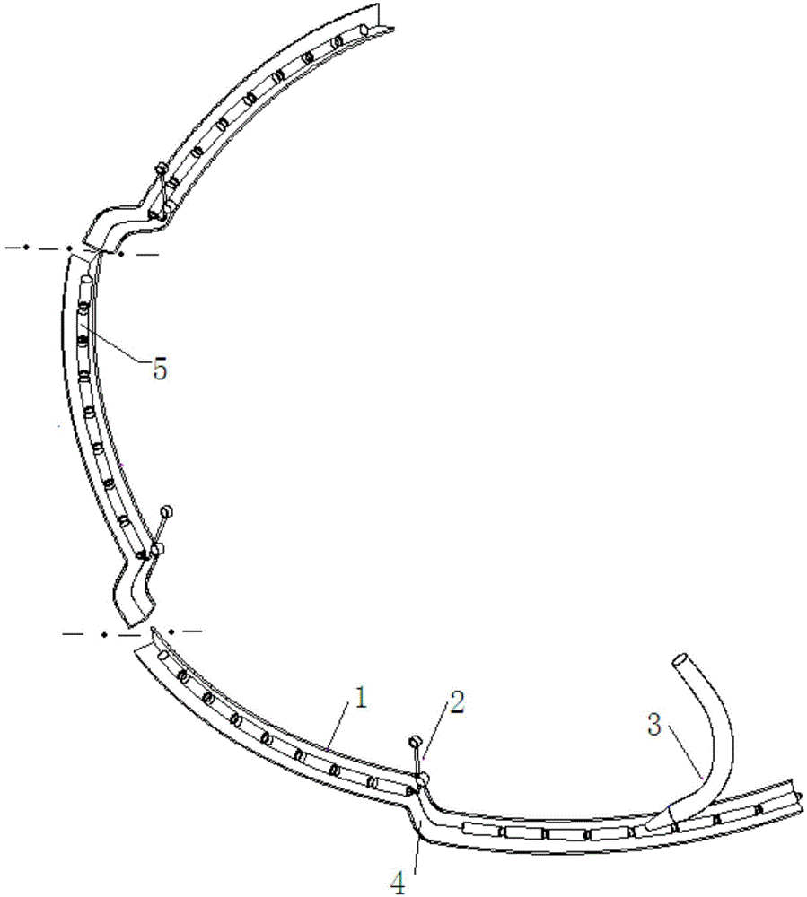
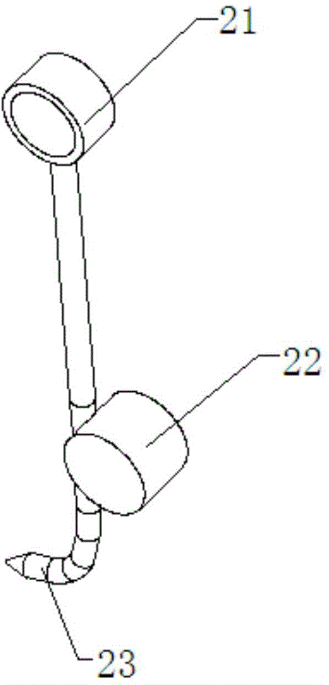
  • Vibration disc type screw conveying device
  • Vibration disc type screw conveying device
  • Vibration disc type screw conveying device

Examples


Embodiment Construction

[0019] It should be noted that, in the case of no conflict, the embodiments of the present invention and the features in the embodiments can be combined with each other.

[0020] The present invention will be described in detail below with reference to the accompanying drawings and examples.

[0021] like Figure 1-3 As shown, a vibrating disc screw conveying device includes a vibrating disc, and the side wall of the vibrating disc is provided with a feeding track 1 spirally raised from the bottom surface of the vibrating disc, and the uppermost layer of the feeding track 1 is provided with a Thermal adjustment screw 5 front and back error correction unit. The front and back error correction unit of the screw 5 makes the front and back of the screw 5 transported to the designated place consistent, which improves production efficiency, improves the qualified rate of screw 5 installation, and saves labor.

[0022] Further, in order to save cost and facilitate production and pr...


PUM


Abstract

The invention provides a vibration disc type screw conveying device which comprises a vibration disc. The side wall of the vibration disc is provided with a feeding rail arranged upwards in a spiral mode from the bottom face of the vibration disc. The top layer of the feeding rail is provided with a forward or reverse screw adjusting unit. The forward or reverse screw adjusting unit comprises an air pipe arranged above the top layer of the feeding rail. The air blowing direction of the air pipe is opposite to the material conveying direction. According to the vibration disc type screw conveying device, the forward or reverse screw adjusting unit is arranged on the top layer of the vibration disc so that screws conveyed to the designated point can be the same in the forward faces and reverse faces, so that production efficiency is improved, meanwhile, the mounted screw yield is increased, and labor can be saved.

Description

technical field [0001] The invention belongs to the field of screw installation devices, in particular to a vibrating disc screw conveying device. Background technique [0002] In the prior art, the installation of heat-adjustable screws on semi-finished circuit breaker shells usually includes two modes: manual screw placement and machine screw delivery, and manual screw placement is inefficient and labor-intensive; machine screw placement is usually conveyed by a vibrating plate, and vibration The forward and reverse directions of the nails conveyed by the disc may be inconsistent, so how to design a vibrating disc screw conveying device that realizes the consistent front and reverse of the screws transported to the designated place has become a research topic for those skilled in the art. Contents of the invention [0003] In view of this, the present invention aims to provide a vibrating disc screw delivery device in which the front and back of the screws delivered to t...

Claims


Application Information

Patent Timeline
Patent Type & Authority Applications(China)
IPC IPC(8): B23P19/00
CPCB23P19/001
Inventor 孙伟李金琪李博宋文宾
Owner TIANJIN DONGMING ELECTRONICS IND
Learn More