
A device and method for detecting backlash in a spiral bevel gear assembly

A technology of spiral bevel gears and detection devices, which is applied in measuring devices and instruments, can solve problems such as complex backlash, troublesome operation, and complex structure of spiral bevel gears, so as to improve the installation qualification rate and reduce meshing abnormal noise and the effect of wear

Active Publication Date: 2021-11-05
ZHUHAI GREE INTELLIGENT EQUIP CO LTD +1
View PDF17 Cites 0 Cited by
  • Summary
  • Abstract
  • Description
  • Claims
  • Application Information

AI Technical Summary

Problems solved by technology

The method of obtaining the backlash of the spiral bevel gear is too complicated, and the required result cannot be directly obtained directly, and its structure is complicated and the operation is troublesome

Method used


Image

  • A device and method for detecting backlash in a spiral bevel gear assembly
  • A device and method for detecting backlash in a spiral bevel gear assembly
  • A device and method for detecting backlash in a spiral bevel gear assembly

Examples


Embodiment 1

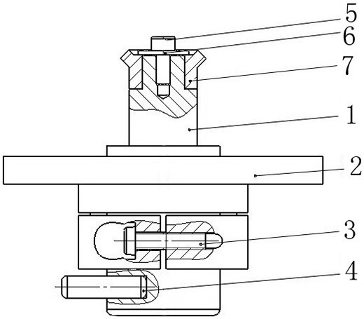
[0032] Embodiment 1: A backlash detection device for spiral bevel gear assembly, such as figure 1 shown.

[0033] A backlash detection device for spiral bevel gear assembly, comprising an adjustment support rod 4, a first bolt 3, a positioning flange 2, an adjustment shaft 1, a gasket 6 and a second bolt 5, and the positioning flange 2 is sleeved on the adjustment shaft 1 outside, the first bolt 3 is installed at the lower part of the positioning flange, the adjusting rod 4 is installed at the lower part of the adjusting shaft 1, and the arc gear 7 to be tested is fixed at the shaft end of the adjusting shaft 1 through the gasket 6 and the second bolt 5.

[0034] In this embodiment, the function of the adjustment rod 4 is to assist the rotation of the adjustment shaft 1 during the adjustment process, which is convenient for operation; the function of the first bolt 3 is to realize the axial stop function of clamping the adjustment shaft 1 adjusted to the theoretical position; ...

Embodiment 2

[0035] Embodiment 2: A method for detecting backlash in a spiral bevel gear assembly, such as Figure 1-5 shown.

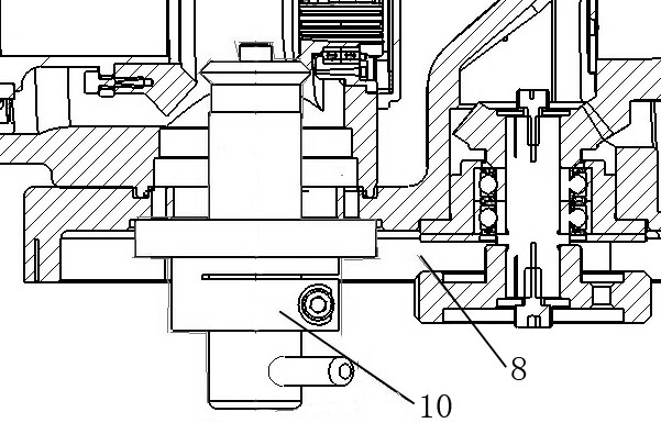
[0036] A method for detecting the backlash of a spiral bevel gear assembly, using the robot joint body 8 pre-installed with the bevel gear and the detection device for the assembly of the spiral bevel gear described in Embodiment 1 to detect the detection size, the specific steps are as follows:

[0037] S1, pre-install and lock the arc gear 7 to be tested to the shaft end of the adjustment shaft 1, and ensure that the shoulder of the adjustment shaft 1 and the end face of the arc gear 7 fit tightly without gaps to avoid measurement errors;

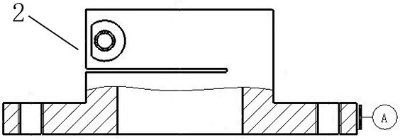
[0038] S2, install the positioning flange 2 on the adjustment shaft 1, the end face of the positioning flange 2 is the installation datum plane, and the outer circular surface of A is the centering datum (such as figure 2 As shown), realize the function of simulating the installation conditions of the original pre-installed...


PUM


Abstract

The invention provides a device and method for detecting backlash in the assembly of a spiral bevel gear. The device includes an adjustment part and a positioning part. The positioning part is set outside the adjustment part. The arc gear to be tested is installed on the adjustment part. The gear and the bevel gear are closely meshed, and reflect the meshing situation of the arc gear and the bevel gear. The positioning part is used to position the position of the adjustment part; the method is to assemble the detection device into the robot joint body to obtain the dimension L1, and the The components are also assembled into the robot joint body to obtain the dimension L2 and the clearance difference ΔL; the device and method for quickly detecting the actual assembly side clearance of the spiral bevel gear proposed by the present invention improve the installation pass rate of the spiral bevel gear , Reduce the abnormal noise and wear of spiral bevel gear meshing.

Description

technical field [0001] The invention relates to the technical field of gear detection, in particular to a device and method for detecting side clearance of a spiral bevel gear assembly. Background technique [0002] Spiral bevel gear transmission is widely used in occasions with large load, high-speed transmission and low noise due to its high load-carrying capacity, stable operation and low noise. The transmission of industrial robot servo motors and reducers is also widely used in the form of spiral bevel gear transmission. [0003] For the high-precision spiral bevel gear transmission structure, its meshing has high requirements on the actual backlash. The corresponding dimensions of the spiral bevel gear itself and the associated structural parts are affected by manufacturing tolerances. There is a large difference between the actual backlash and the theoretical backlash in the installation process of the spiral bevel gear, and present different characteristics, which d...

Claims


Application Information

Patent Timeline
Patent Type & Authority Patents(China)
IPC IPC(8): G01B21/16
CPCG01B21/16
Inventor 谢慧军吴继青陆明谢黎曾庆新李明
Owner ZHUHAI GREE INTELLIGENT EQUIP CO LTD
Learn More