High-frequency power amplifier

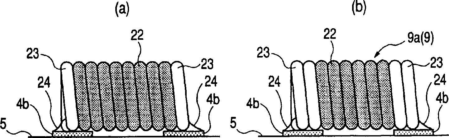
A power amplifying and high-frequency technology, applied in the field of high-frequency power amplifying devices, can solve the problems that the capturing cylinder 32 cannot be reliably vacuum-adsorbed to hold and transport the hollow coil 9, the vacuum adsorption force of the capturing cylinder is increased, and the coil arrangement is disordered, etc. Installation cost, efficient installation work, and the effect of reliable installation

Inactive Publication Date: 2006-05-17
HITACHI LTD +2
View PDF0 Cites 0 Cited by
  • Summary
  • Abstract
  • Description
  • Claims
  • Application Information

AI Technical Summary

Problems solved by technology

[0037] However, as mentioned above, since the hollow coil is extremely light, it is easy to move due to changes in air flow (air pressure) or vibration during vacuum suction switching, such as Figure 44 As shown, the front and rear air core coils 9 overlap between the ends
At this time, the capture cylinder 32 cannot reliably vacuum hold and transport the hollow coil 9, and the hollow coil 9 cannot be mounted on the module substrate.
In addition, although the vacuum suction force generated by the capture cylinder can be increased, if the vacuum suction force is large, the arrangement of the coils will be disordered due to the influence of the vacuum suction force, and the vacuum suction force of the capture cylinder cannot be increased more than necessary. easy to control

Method used


Image

  • High-frequency power amplifier
  • High-frequency power amplifier
  • High-frequency power amplifier

Examples


Embodiment Construction

[0127] Hereinafter, embodiments of the present invention will be described in detail with reference to the drawings. In addition, in all the drawings for explaining the embodiments of the present invention, parts having the same functions are denoted by the same reference numerals, and overlapping descriptions are omitted.

[0128] (Embodiment 1)

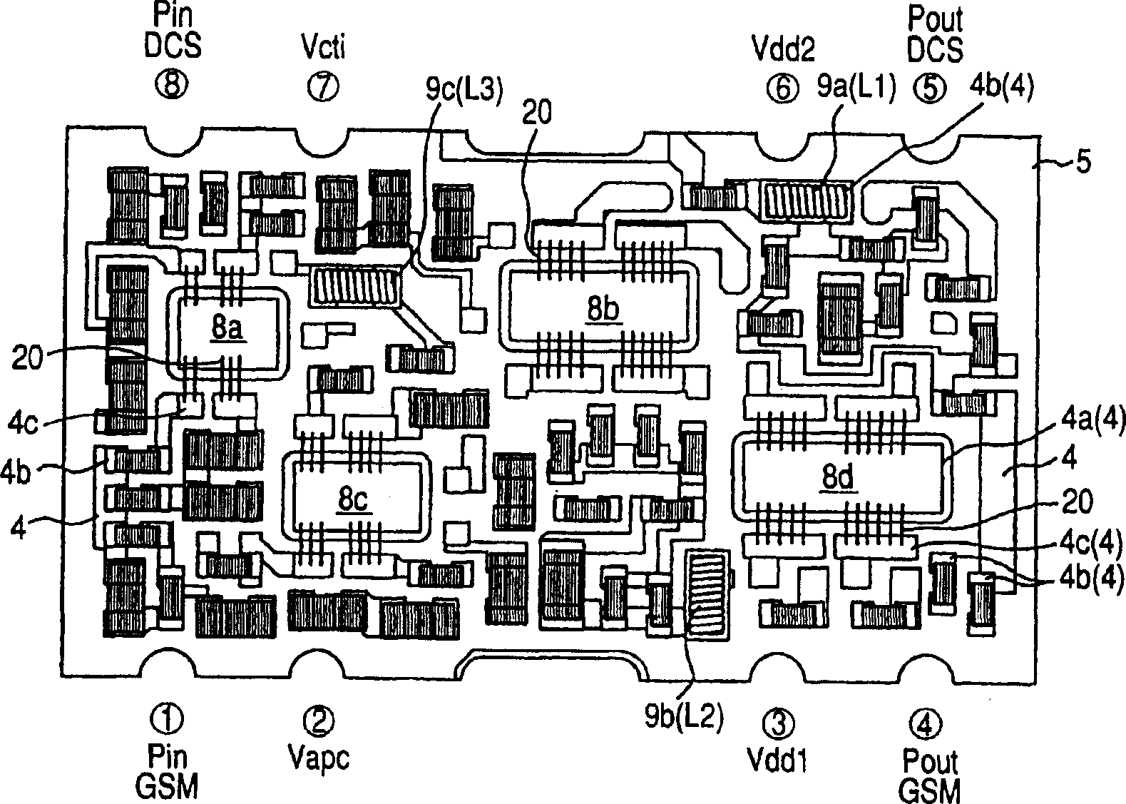
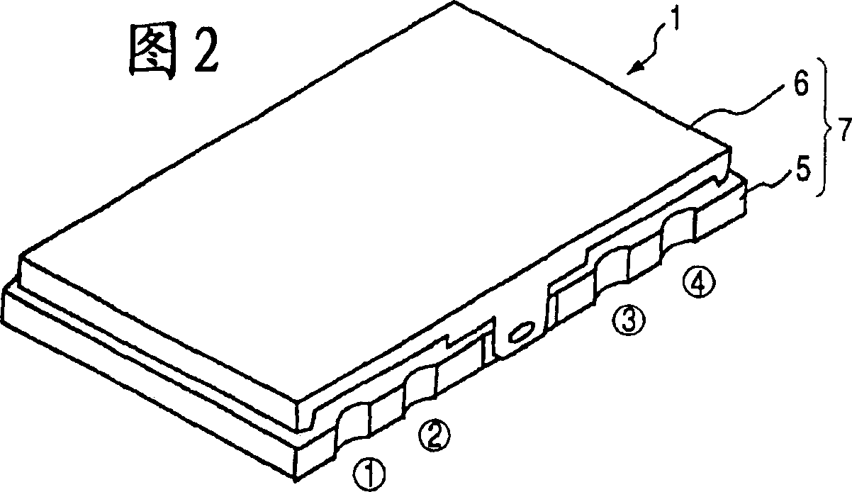
[0129] Figure 1 to Figure 31 It is a diagram of a semiconductor device (high-frequency power amplifying device) and its manufacturing technology and a wireless communication device (electronic device) according to one embodiment (Embodiment 1) of the present invention.

[0130] In Embodiment 1, an example in which the present invention is applied to a high-frequency power amplifying device (hybrid integrated circuit device) as a semiconductor device will be described. The high-frequency power amplifying device of the first embodiment is for dual-band, and is a high-frequency power amplifying device for dual-band built in, for exa...


PUM

PropertyMeasurementUnit
lengthaaaaaaaaaa
weightaaaaaaaaaa
electrical resistanceaaaaaaaaaa

Abstract

A high-frequency power amplifying device has two amplifying systems. The amplification system is a structure in which multiple amplification stages are connected in series. The power supply voltage terminal is two terminals. One power supply voltage terminal is respectively connected to the primary amplification stage of one amplification system and the remaining amplification stages of the other amplification system. The other power supply The voltage terminals are respectively connected to the primary amplifier stage of the other amplifier system and the remaining amplifier stages of the one amplifier system. A copper wire with a diameter of about 0.1 mm is tightly wound into a helical air-core coil with a small DC resistance and connected in series between the final amplification stage of each amplification system and the power supply voltage terminal. The signal leakage from the final amplification stage to the primary amplification stage does not occur in each amplification system, and the oscillation tolerance can be improved because the DC resistance of the air-core coil is small. The air-core coil is inexpensive, and it is possible to reduce the cost of the high-frequency power amplifying device. The air core coils are supplied with a bulk feeder and mounted on the module substrate.

Description

technical field [0001] The present invention relates to a semiconductor device, a manufacturing method thereof, and a semiconductor manufacturing device, for example, to a manufacturing technique of a high-frequency power amplifying device (high-frequency power amplifying module) having a multi-stage structure in which a plurality of amplifiers are connected in series as a semiconductor device, And it is an effective technology applied to wireless communication devices (electronic devices) such as mobile phones incorporating the high-frequency power amplifying device. Background technique [0002] The high-frequency power amplifying device used in wireless communication devices such as car phones and mobile phones has a structure in which multiple amplifiers composed of semiconductor amplifying elements (transistors) are connected in series to form a multi-stage multi-stage structure such as two-pole or three-stage . The amplifier of the last stage of the multi-stage struct...

Claims


Application Information

Patent Timeline
Patent Type & Authority Patents(China)
IPC IPC(8): H01F17/02H01F41/00H03F3/60H03F3/72H01F27/29H01L25/04H01L23/64H01L23/66H04B1/04H05K1/18H05K13/02
CPCH01F17/02H01F27/292H01L23/645H01L23/66H01L2223/6644H01L2224/48227H01L2224/49175H01L2924/01012H01L2924/01046H01L2924/01078H01L2924/09701H01L2924/14H01L2924/15313H01L2924/19041H01L2924/19104H01L2924/19105H01L2924/30107H01L2924/3011H01L2924/3025H03F3/602H03F3/72H03F2200/429H03F2203/7236H04B2001/0408H05K1/181H05K13/028H01L24/48H01L24/49H01L2224/45147H01L2924/01047H01L2924/01015H01L2924/12041H01L2224/45015H01L2924/00014H01L2924/12042H01L24/45H03F3/24Y02P70/50H01L2924/00H01L2924/2076H01L2224/05599H01L25/04
Inventor 京極敏彦神津正望月清春石津昭夫小林义彦佐藤勧菊池荣丸山昌志神代岩道
Owner HITACHI LTD
Why Eureka
Try Eureka