Tray mold for easy injection molding of feet

A foot and tray technology is applied in the field of tray molds that are convenient for injection molding of feet. The effect of improving the yield

Active Publication Date: 2017-06-27
ZHEJIANG XINDING PLASTIC +1
View PDF4 Cites 4 Cited by
  • Summary
  • Abstract
  • Description
  • Claims
  • Application Information

AI Technical Summary

Problems solved by technology

This will lead to the fact that the plastic cannot fill the cavity at the foot during the injection molding process, resulting in the injection thickness of the foot not meeting the standard, resulting in insufficient structural strength, or low efficiency due to too long injection time

Method used


Image

  • Tray mold for easy injection molding of feet
  • Tray mold for easy injection molding of feet
  • Tray mold for easy injection molding of feet

Examples


Embodiment Construction

[0016] refer to Figure 1 to Figure 5 Further description will be given to the embodiment of the tray mold for convenient injection molding feet of the present invention.

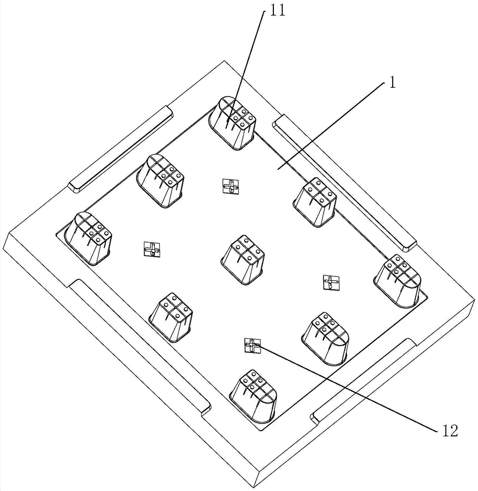
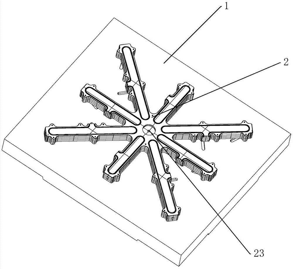
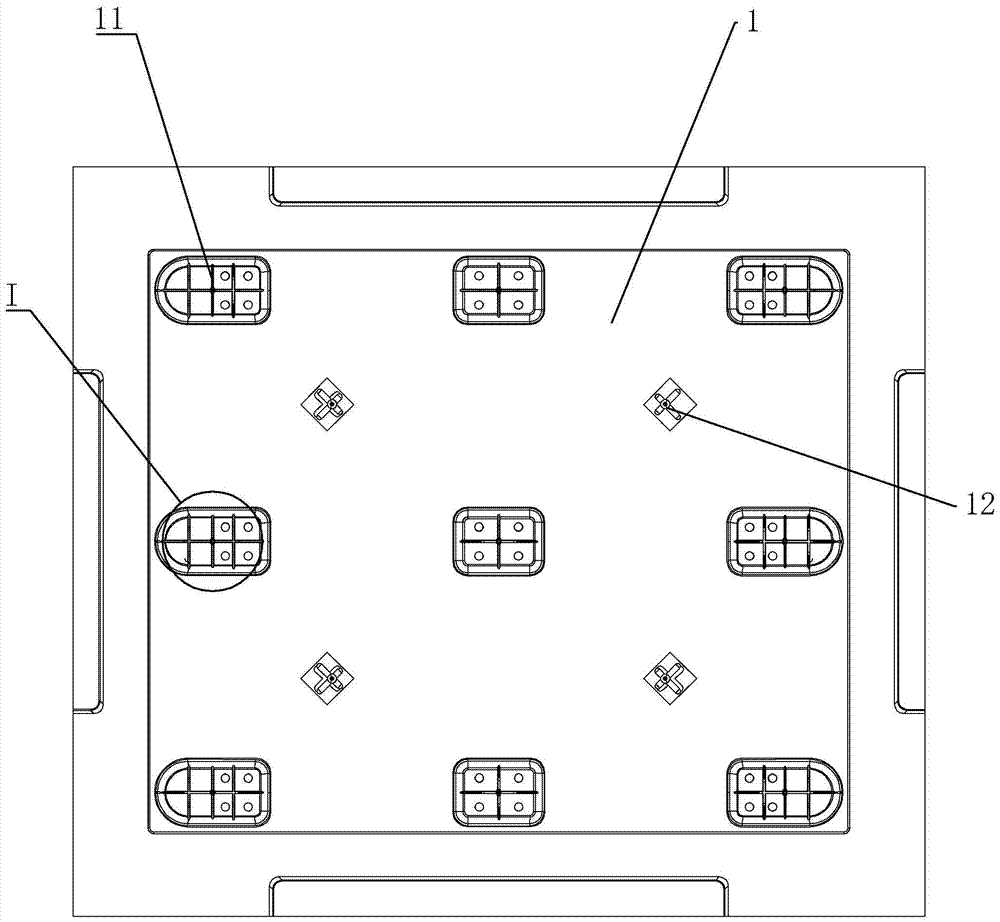
[0017] A pallet mold for convenient injection molding feet, comprising a fixed mold 1 and a movable mold, the fixed mold 1 is a rectangular formwork, the fixed mold 1 is provided with several protrusions 11 for injection molding feet, and the movable mold is above A concave portion corresponding to the protruding portion 11 is provided, and the protruding portion 11 and the concave portion jointly constitute a processing mold cavity of the foot.

[0018] Such as figure 1 or 3, the protruding portion 11 is provided with a first gate 111 for injection molding, and the plate surface of the fixed mold 1 is provided with a second gate 12, and the second gate 12 is connected to the The first gate 111 is located on the same surface of the fixed mold 1 . Such as figure 2 or 4, the other side of the fixed mold ...


PUM


Abstract

The invention discloses a tray mold facilitating injection molding of bottom feet. According to the technical scheme, the tray mold is characterized in that the tray mold comprises a fixed mold body and a movable mold body; the fixed mold body is provided with a plurality of protrusions for injection molding of the bottom feet; first sprues for injection molding are arranged on the protrusions; second sprues are arranged on the plate face of the fixed mold body; the second sprues and the first sprues are located on the same face of the fixed mold body; a feeding frame for being communicated with the first sprues and the second sprues is arranged on the other face of the fixed mold body; an injection molding opening connected with a nozzle of an injection molding machine is arranged on the feeding frame. One sprue is additionally arranged on each protrusion of the fixed mold body, it is ensured that injection molding of the tray bottom feet can reach the standard, and meanwhile injection molding efficiency is improved.

Description

technical field [0001] The present invention relates to a mold, more specifically, it relates to a tray mold for convenient injection molding of feet. Background technique [0002] Injection mold is a tool for producing plastic products, which can mass produce some plastic parts with complex shapes. The injection mold is usually composed of a movable mold and a fixed mold. During production, the mold is installed in the injection molding machine, and the injection molding machine is used to inject the heated and melted plastic into the cavity of the injection mold by high pressure. After cooling and solidification, the injection molding machine pulls The movable mold is separated from the fixed mold, and then the injection-molded finished product is pushed out by the ejector mechanism to complete one injection. [0003] In the process of injection molding larger plastic products, the molten plastic on the injection molding machine is injected into the cavity through multipl...

Claims


Application Information

Patent Timeline
Patent Type & Authority Patents(China)
IPC IPC(8): B29C45/26B29C45/27
CPCB29C45/26B29C45/2708B29C2045/2709
Inventor 陈爱华
Owner ZHEJIANG XINDING PLASTIC
Why Eureka
Try Eureka