Printing slotting die-cutting machine with a spiral lifting adjustment apparatus in the printing portion

A technology of screw lifting and adjusting device, applied in packaging, transportation and packaging, container manufacturing machinery and other directions, can solve problems such as affecting the quality of carton prints, deviation of the height of suction and feeding cartons, and inability to meet market requirements.

Inactive Publication Date: 2015-09-23
上海鼎龙机械有限公司
View PDF6 Cites 0 Cited by
  • Summary
  • Abstract
  • Description
  • Claims
  • Application Information

AI Technical Summary

Problems solved by technology

With the advancement of technology, the printing accuracy of the printing slotting die-cutting machine is required to be higher, and the adjustment of the height of the suction carton on the existing printing slotting die-cutting machine is to lift the suction through the rotation of four eccentric cams. The two longitudinal eccentric cams straddle the two ends of a slender camshaft. The eccentric cam at the other end of the camshaft has a deflection deviation due to the slenderness of the camshaft. The rotation angles of the two longitudinal eccentric cams are inconsistent, resulting in a deviation in the height of the suction carton. The worse this phenomenon is, the worse the printing effect will be, which seriously affects the quality of the carton printed matter.
In order to improve the printing quality, it is necessary to provide a solution that can be solved on the traditional printing slotting die-cutting machine, so that a large number of small and medium-sized carton enterprises can print high-quality products more quickly and economically without increasing the burden to meet the production requirements. The needs of different carton products and the existing technical methods are no longer suitable for market requirements

Method used


Image

  • Printing slotting die-cutting machine with a spiral lifting adjustment apparatus in the printing portion
  • Printing slotting die-cutting machine with a spiral lifting adjustment apparatus in the printing portion
  • Printing slotting die-cutting machine with a spiral lifting adjustment apparatus in the printing portion

Examples


Embodiment Construction

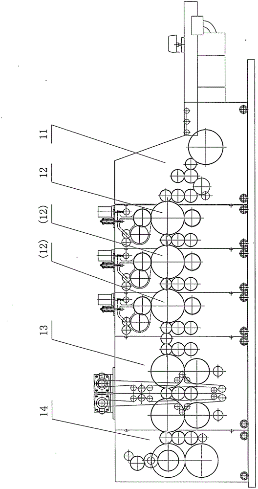
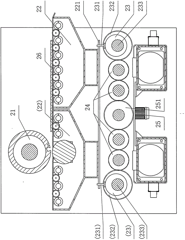
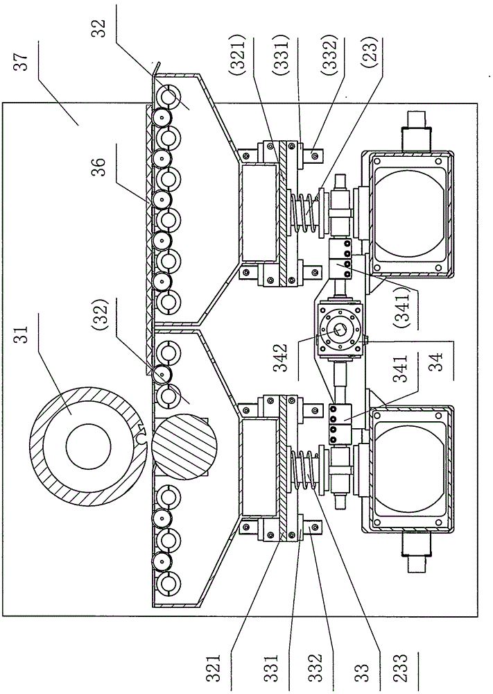
[0010] The main structure of the printing slotting die-cutting machine with the spiral lifting adjustment device in the printing part of the present invention is as follows: figure 1 As shown, it mainly includes paper feeding unit, multiple printing units, slotting unit and die-cutting unit. The printing part is equipped with a spiral lifting adjustment device, the main structure is as follows: image 3 , Figure 4 As shown, between the two wallboards 37 and 38 of the printing section of the printing slotting die-cutting machine, two groups of air-suction cartons 32 are installed, and a liner 321 is respectively fixed at both ends of the bottom of each group of air-suction cartons. The liner is fixedly connected with the sliders 321 mounted on the two movable slides inside the wallboard. Under each liner 321, there is a screw lifter 33 on the top. The two screw lifters 33 in the horizontal direction pass through the coupling. 341 is connected with a T-type coupling 34, and t...


PUM


Abstract

The invention discloses a printing slotting die-cutting machine with a spiral lifting adjustment apparatus in the printing portion thereof, including a lifting adjustment apparatus which is mounted with the two internal sides of the wall boards, and is composed of two sets of movable sliding seats and two sets of spiral lifting means, two T-shaped couplers and a turbine decelerator. The printing slotting die-cutting machine herein is characterized in that: each set of the movable sliding seat is respectively composed of four sliding blocks and sliding rails, each two sliding blocks and each two sliding rails being in relative arrangement within the two internal sides of the wall boards, each two sliding blocks being in fixed coupling with one end of an air-absorbing paper feeding box through a liner plate, the liner plates at the two ends of the air-absorbing paper feeding boxes being supportedly against two spiral lifting means at the lower ends of the liner plates, among the two spiral lifting means under the two sets of the air-absorbing paper feeding boxes, the two spiral lifting means being transversely coupled to one T-shaped coupler through a coupling and longitudinally the T-direction output end of the two T-shaped couplers being respectively connected to one turbine decelerator through a connecting rod such that the two sets of the air-absorbing paper feeding boxes form an integral synchronizing lifting means, thus guaranteeing unanimity of lifting heights of the air-absorbing paper feeding boxes.

Description

technical field [0001] The invention relates to a packaging machine, in particular to a printing slotting die-cutting machine, the printing part of which is provided with a spiral lifting adjustment device. Background technique [0002] Printing slotting die-cutting machine is a widely used packaging machinery, its main structure is as follows figure 1 As shown, it includes a paper feeding unit 11, a plurality of printing units 12, a slotting unit 13 and a die-cutting unit 14, and each unit works in a unified and coordinated manner under the action of the power equipment and the transmission mechanism to jointly complete the paper feeding, printing, and printing of the cardboard. Grooving and die cutting. Among them, the printing part is equipped with a spiral lifting adjustment device, including a lifting adjustment device installed on both sides of the printed wallboard, consisting of two sets of moving slides, two sets of screw lifting devices, two T-shaped couplings and...

Claims


Application Information

Patent Timeline
Patent Type & Authority Applications(China)
IPC IPC(8): B31B1/04B31B1/88B31B1/22B31B50/04B31B50/22B31B50/88
Inventor 丁根龙
Owner 上海鼎龙机械有限公司
Why Eureka
Try Eureka