Electromagnetic chuck lifting mechanism for section steel stacker crane and control method thereof

A technology of electromagnetic chuck and lifting mechanism, which is applied in the field of palletizing, can solve the problems of high manufacturing cost, poor synchronization performance, cumbersome installation and maintenance, etc., and achieve the effect of low manufacturing cost, high synchronization and easy operation

Pending Publication Date: 2019-01-08
马钢集团设计研究院有限责任公司
View PDF2 Cites 0 Cited by
  • Summary
  • Abstract
  • Description
  • Claims
  • Application Information

AI Technical Summary

Problems solved by technology

[0007] Aiming at the problem that the lifting of the electromagnetic sucker of the existing palletizer uses multiple hydraulic cylinders in parallel, the synchronization performance is poor, the installation and maintenance are cumbersome, and the manufacturing cost is high. The invention provides an electromagnetic sucker lifting mechanism for a steel palletizer and its Control Method

Method used


Image

  • Electromagnetic chuck lifting mechanism for section steel stacker crane and control method thereof
  • Electromagnetic chuck lifting mechanism for section steel stacker crane and control method thereof
  • Electromagnetic chuck lifting mechanism for section steel stacker crane and control method thereof

Examples


Embodiment 1

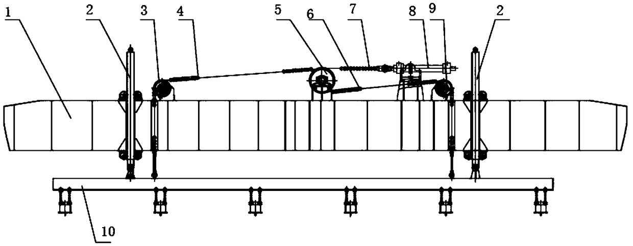
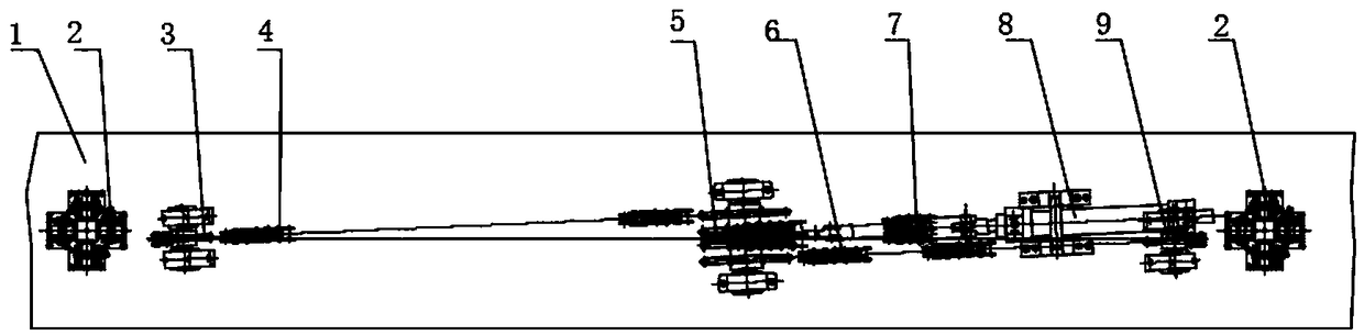
[0045] Such as figure 1 and figure 2 As shown, an electromagnetic sucker lifting mechanism for a section steel palletizer includes a beam 1, the beam 1 is a welded workpiece, the welding process is simple and the joint strength is high, so that the beam 1 has high strength; the upper and lower ends of the beam 1 There are several supports between them, including the left steering sprocket 3, the left chain 4, the synchronous sprocket 5, the right chain 6, the drive chain 7, the oil cylinder 8, the right steering sprocket 9 and the electromagnetic chuck device 10 , the left steering sprocket 3, the synchronous sprocket 5, the oil cylinder 8 and the right steering sprocket 9 are sequentially fixed on the support between the upper and lower end faces of the beam 1 through a fastening device. Preferably, the fastening device For fastening bolts or fastening screws, the structure is simple, the stability is good, and the cost is low; other fastening devices known to the public ca...

Embodiment 2

[0050] Basically the same as embodiment 1, such as Figure 5 and Figure 6 As shown, this embodiment also includes a guide device 2, the installation position of the guide device 2 on both sides of the beam 1 is provided with a through guide hole, the guide device 2 passes through the guide hole and is arranged symmetrically along the center of the beam 1, and the setting of two guide devices 2 is effective It avoids the shaking of the electromagnetic chuck device 10 during the lifting process, and ensures that the section steel has good stability during the lifting process; the guide device 2 includes a guide rod 21 and several guide wheels 22; preferably, the guide wheels 22 are Eight, eight guide wheels 22 are divided into two groups, and each group of four guide wheels 22 is symmetrically distributed in a "ten" shape, and each group of guide wheels 22 is connected with the support on the beam 1 through a fastening device. The device is a fastening bolt or a fastening scre...

Embodiment 3

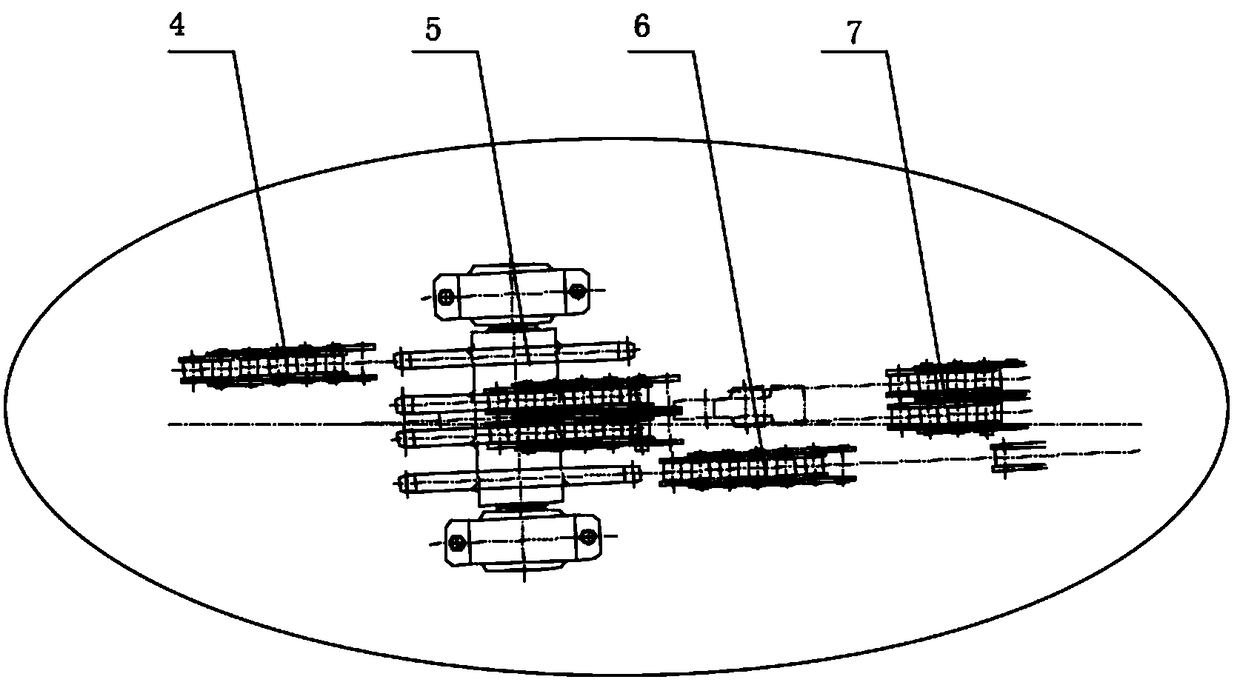
[0052] Basically the same as embodiment 1, preferably, one end of the left chain 4 and one end of the right chain 6 are provided with a fork with a stud adjustment device, and the fork and the connecting beam 101 in the electromagnetic chuck device 10 pass through the pin Connection, the other end of the left chain 4 and the other end of the right chain 6 are connected to the synchronous sprocket 5 through the corresponding pin hole in the synchronous sprocket 5; during the initial assembly or later use, due to the length error or wear of the chain, The connecting beam 101 is tilted and the lifting of the whole device is hindered. At this time, by adjusting the stud adjustment device at the fork of the left chain 4 and the right chain 6, the connecting beam 101 is adjusted to a horizontal posture, and the connecting beam 101 is monitored in real time. The state and timely adjustment, the whole process is easy and timely to operate, so that the safety performance and synchroniza...


PUM


Abstract

The invention discloses an electromagnetic chuck lifting mechanism for a section steel stacker crane and control method thereof and relates to the technical field of section steel palletizing. In viewof the poor lifting synchronization performance of an existing stacker crane and cumbersome installation and maintenance, high cost, the electromagnetic chuck lifting mechanism for section steel stacker crane is provided, wherein a beam is included. A plurality of supports are arranged between the upper end face and the lower end face of the beam. A left steering sprocket, a synchronous sprocket,an oil cylinder and a right steering sprocket are all fixed on the supports through fastening devices. A left side chain, a right side chain and a driving chain are connected with the synchronous sprocket respectively. An electromagnetic chuck device is arranged below the beam. The hydraulic synchronization is changed to sprocket and chain synchronization, single oil cylinder driving is arranged,so that the synchronization performance of whole device is good. The control method of the electromagnetic chuck lifting mechanism for the section steel stacker crane is provided, the oil cylinder isstarted to drive a sprocket and a chain to rotate, the lifting of the electromagnetic chuck is achieved, and operability is strong.

Description

technical field [0001] The invention belongs to the technical field of stacking in a section steel rolling production line, and more specifically relates to an electromagnetic sucker lifting mechanism for a section steel stacker and a control method thereof. Background technique [0002] Section steel stacking is an important link in the process of section steel production, bundling, transportation and storage. The section steel palletizer is mainly arranged in the rear section of the finishing area of ​​the section steel rolling production line, and is used for stacking the fixed-size section steel cut by the cold saw into a specified stacking shape. [0003] Existing section steel palletizers mostly adopt several main forms such as traversing electromagnetic palletizing, traversing-turning electromagnetic palletizing, and pendulum electromagnetic palletizing. Because of its relatively simple structure and reliability, the transverse-moving electromagnetic palletizer is wi...

Claims


Application Information

Patent Timeline
Patent Type & Authority Applications(China)
IPC IPC(8): B65G47/92B65G61/00B65G43/00
CPCB65G47/92B65G43/00B65G61/00B65G2203/042
Inventor 徐旭马寅东鲁照亮周奎王勇张洪为唐明姣
Owner 马钢集团设计研究院有限责任公司
Why Eureka
Try Eureka