Method for forming annular halo

A ring-shaped, optical groove technology, applied in the field of lenses, can solve the problems of obvious light spots, uneven light distribution, clear boundaries, etc., and achieve the effect of increasing the number of reflections, improving the utilization rate, and good use effect

Active Publication Date: 2015-09-23
HENGDIAN GRP TOSPO LIGHTING
View PDF3 Cites 5 Cited by
  • Summary
  • Abstract
  • Description
  • Claims
  • Application Information

AI Technical Summary

Problems solved by technology

The usual conjoined lens is equivalent to a simple combination of multiple lenses. Although the uniformity of refracted light distribution has been improved to a certain extent, there are still problems such as uneven light distribution, obvious light spots, and too clear boundaries, which is not conducive to the illumination gradient of lighting equipment. Distributed but uniform diffuse light effect

Method used


Image

  • Method for forming annular halo
  • Method for forming annular halo
  • Method for forming annular halo

Examples


Embodiment 1

[0036] Such as Figure 1~5 Shown, a kind of method for forming annular halo, comprises the steps:

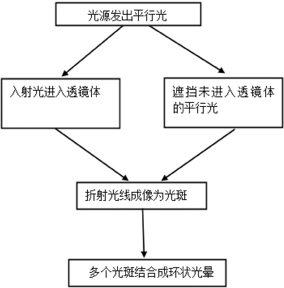
[0037] (a) The light source emits parallel light;

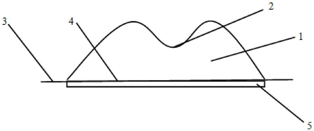
[0038] (b) Parallel light enters the lens body 1 with the light guide groove 5 at the bottom, and the lens body 1 has a concave structure in the middle and has a concave low point 2;

[0039] (c) When the parallel light enters the lens body 1, the parallel light that does not enter the lens body 1 is blocked;

[0040] (d) using a screen or similar device to image the refracted light refracted by the lens body 1;

[0041] (e) At the same time, on the same geometric plane, repeat the above steps (a) to (d) in the manner of uniform distribution on the concentric circle to form a plurality of light spots refracted by the lens body 1, and the multiple light spots are finally Form a ring halo.

[0042] In the method for forming an annular halo in this embodiment, the number of repetitions of the step (e) is 12 times. The cross s...

Embodiment 2

[0046] The difference between this embodiment and Embodiment 1 lies in that the cross section of the lens body 1 in the step (b) described in this embodiment is circular. There are 2 concentric circles in the step (e); repeat step (e) 12 times on each concentric circle. The ratio of the distance from the concave low point 2 to the lens bottom surface 4 in step (b) of this embodiment to the distance from the highest point of the lens body 1 to the lens bottom surface 4 is 1:5.

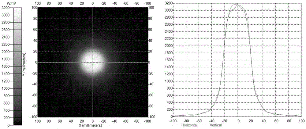
[0047] During the implementation of this embodiment, the parallel light emitted by the light source enters through the light guide groove 5, such as figure 2 The shown lens body 1 becomes as follows under the refraction of a single lens body 1 image 3 The spots shown. From image 3 It can be seen that the distribution of a single spot is formed by the superposition of two beams of light. The two beams of light complement each other to avoid uneven brightness and darkness in the center. The outside ...


PUM


Abstract

The invention discloses a method for forming annular halo. The method includes the steps: (a) emitting parallel light by a light source; (b) irradiating a lens (1) with a light guide groove (5) at the bottom by the parallel light; (c) shading the parallel light not entering the lens (1) while irradiating the lens (1) by the parallel light; (d) imaging a refracted ray refracted by the lens (1) by the aid of a screen or similar device; (e) repeating the steps (a) to (d) to form a plurality of light spots by refraction of the lens (1) in a uniformly distributed mode on a concentric circumference at the same time and on the same geometric plane. The middle of the lens (1) is structurally recessed, and the lens (1) is provided with a recessed low point (2). The light spots finally form the annular halo. Diffused light with illumination in graded distribution and uniform gradual change can be manufactured, so that a user feels comfortable and lazy under the light, and the method can be used for hypnotic illumination of a sleep lamp.

Description

technical field [0001] The invention relates to lens technology, in particular to a method for forming an annular halo. Background technique [0002] The refraction of light by ordinary lenses can only produce general effects, and the uniform distribution of light is not good. In order to enhance the uniformity of light dispersion, multiple lenses need to be used, and multiple lenses can be connected in one plane to form a conjoined lens. The usual conjoined lens is equivalent to a simple combination of multiple lenses. Although the uniformity of refracted light distribution has been improved to a certain extent, there are still problems such as uneven light distribution, obvious light spots, and too clear boundaries, which is not conducive to the illumination gradient of lighting equipment. A diffuse light effect that is distributed but gradients evenly. The diffuse light effect with gradient distribution of illuminance but uniform gradient is often used for special situa...

Claims


Application Information

Patent Timeline
Patent Type & Authority Applications(China)
IPC IPC(8): F21V13/00F21V5/04F21V1/00
CPCF21V1/00F21V5/04F21V13/00
Inventor 梁培王璟陈超杜罡
Owner HENGDIAN GRP TOSPO LIGHTING
Why Eureka
Try Eureka