A Method of Compensating the Signal Amplitude of Broadband Sonar System

A technology for transmitting signals and acoustic signals, which is applied in the field of compensating the amplitude of signals transmitted by broadband sonar systems, and can solve problems such as increasing the difficulty of transmitting system design and the difficulty of high-order matching circuits

Active Publication Date: 2017-06-20
HARBIN ENG UNIV
View PDF3 Cites 0 Cited by
  • Summary
  • Abstract
  • Description
  • Claims
  • Application Information

AI Technical Summary

Problems solved by technology

Since the transfer function of the actual transducer is difficult to be expressed by an analytical function and the components that make up the matching circuit are not ideal components, it is very difficult to realize the required high-order matching circuit, which increases the design difficulty of the entire transmitting system

Method used


Image

  • A Method of Compensating the Signal Amplitude of Broadband Sonar System
  • A Method of Compensating the Signal Amplitude of Broadband Sonar System
  • A Method of Compensating the Signal Amplitude of Broadband Sonar System

Examples


specific Embodiment approach 1

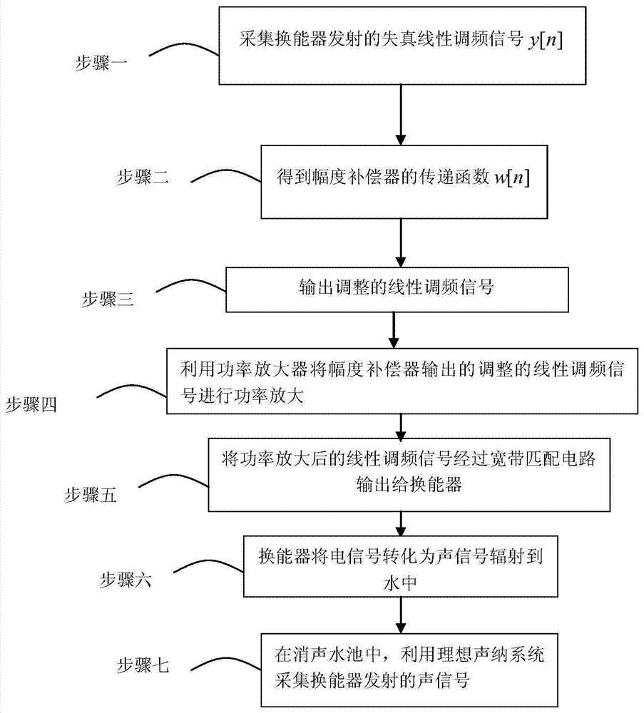
[0089] Specific implementation mode 1: A method for compensating the signal amplitude transmitted by a broadband sonar system in this implementation mode is specifically prepared according to the following steps:

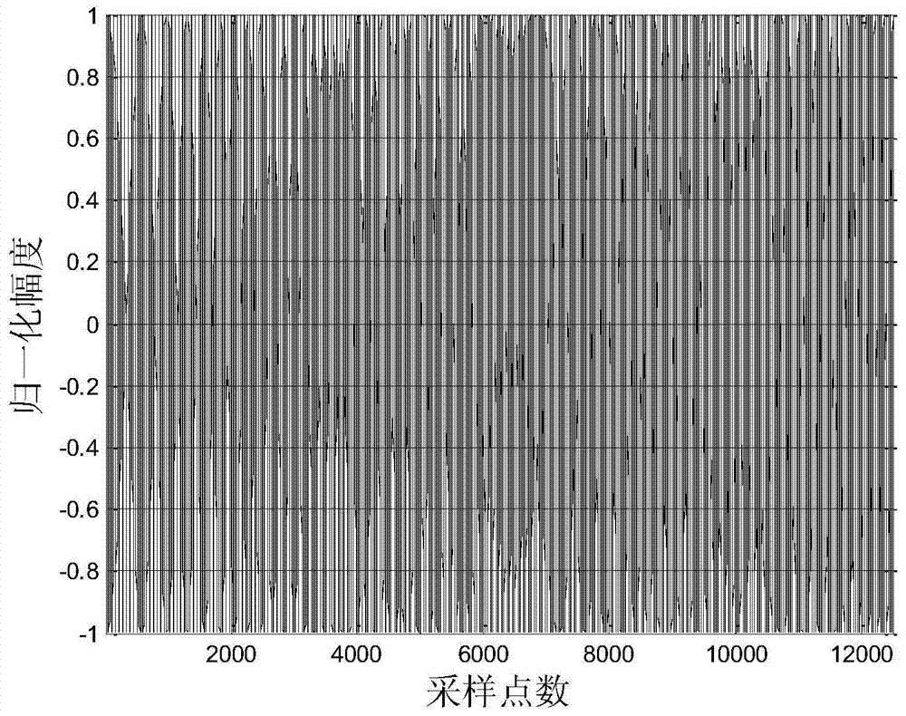
[0090] Step 1. The sonar transmitting system transmits the ideal chirp signal x 0 [n] As shown in Figure 3(a) and Figure 3(b), in the anechoic pool, use the ideal sonar receiving system to collect the distorted chirp signal y[n] emitted by the transducer, as shown in Figure 5(a) and Figure 5 (b); Wherein, sonar transmitting system is made up of ideal signal source, power amplifier, broadband matching circuit and transducer, and its bandwidth of described ideal chirp signal is the working bandwidth of sonar transmitting system, and concrete composition connection mode is as follows figure 2 As shown, the amplitude-frequency response of the broadband matching circuit and the transducer is as follows Figure 4 shown;

[0091] Step 2. Combine the distorted chirp sign...

specific Embodiment approach 2

[0097] Specific embodiment two: the difference between this embodiment and specific embodiment one is: in step one, the sonar transmitting system transmits the ideal chirp signal x 0 [n] As shown in Figure 3(a) and Figure 3(b), in the anechoic pool, the ideal sonar receiving system is used to collect the distorted chirp signal y[n] emitted by the transducer. The specific process:

[0098] (1) Carry out power amplification through ideal chirp signal through power amplifier;

[0099] (2) Output the amplified ideal chirp signal to the transducer through a broadband matching circuit;

[0100] (3) The transducer converts the electrical signal into an acoustic signal (distorted chirp signal) and radiates it into the water;

[0101] (4) The ideal sonar system uses the collector to collect the distorted chirp signal emitted by the transducer in water, as shown in Figure 5(a) and Figure 5(b);

[0102] Described ideal sonar receiving system is to use standard hydrophone and measuring ...

specific Embodiment approach 3

[0103] Specific implementation mode three: the other steps of this implementation mode are the same as those in specific implementation mode one or two, the difference is that the broadband matching network design process in step one is specifically:

[0104] (1) Use an impedance analyzer to test the input impedance data Z of the transducer l (s);

[0105] (2) Using impedance data Z l (s) Calculate the output impedance function Z of the matching network q (s);

[0106] (3) According to Z q (s) The realized structure and parameters of the calculated broadband matching network. Other steps and parameters are the same as those in Embodiment 1 or Embodiment 2.


PUM


Abstract

The invention discloses a method for compensating the amplitude of an emission signal of a broadband sonar system. The method comprises the following steps that a sonar emission system emits an ideal chirp signal x0[n], and an ideal sonar reception system is used to collect a distorted chirp signal y[n] in a soundproofing water pool; an error function e[n] is constructed, an estimated value, which satisfies the condition of min{E[e2[n]]}, of a transfer function of a broadband matching network and an energy transducer is searched, and a transfer function w[n] of an amplitude compensator is obtained; the amplitude compensator adjusts the amplitude of the ideal chirp signal; the power of the adjusted chirp signal is amplified; the power-amplified chirp signal is output to the energy transducer via the broadband matching network; the energy transducer converts an electrical signal into an acoustic signal and radiates the acoustic signal to water; and the ideal sonar reception system is used to collect the acoustic signal emitted by the energy transducer in the soundproofing water pool. The method can be used to reduce amplitude distortion of the emission signal, and has the advantage of high precision.

Description

technical field [0001] The invention belongs to the field of sonar signal transmission, in particular to a method for compensating the signal amplitude transmitted by a broadband sonar system. Background technique [0002] In the design of broadband sonar system, the broadband transducer is an important part of the transmitting system. Generally, the transmission voltage response fluctuation of the transducer within the bandwidth is within 3dB, but in some broadband transducers, the transmission voltage response fluctuation is 5-10dB. When the transducer transmits a broadband signal, the emitted acoustic signal will produce Amplitude distortion. In the corresponding receiving sonar system, when the processor processes the distorted signal, the obtained signal characteristic parameters cannot meet the set value of the detector. The signal characteristic parameters can include: signal amplitude, frequency, signal correlation amplitude, etc., so the distortion The signal will...

Claims


Application Information

Patent Timeline
Patent Type & Authority Patents(China)
IPC IPC(8): G01S7/52
CPCG01S7/52G01S7/52004G01S7/534
Inventor 孙大军王永恒刘璐勇俊张殿伦张友文
Owner HARBIN ENG UNIV
Why Eureka
Try Eureka