
Method, PE equipment and system for linear protection switching

A linear protection switching and equipment technology, applied in the field of network communication, can solve problems such as being unable to respond to input, affecting the controllable and manageable characteristics of equipment, etc.

Active Publication Date: 2018-05-08
RAISECOM TECH
View PDF6 Cites 0 Cited by
  • Summary
  • Abstract
  • Description
  • Claims
  • Application Information

AI Technical Summary

Problems solved by technology

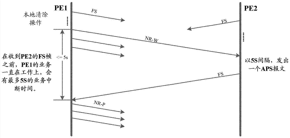
The above method needs to use the state carried by the most recently received APS message stored in the memory to mark the remote state. Usually, the APS protocol sent by the remote device to the near-end device is usually sent at an interval of 5s; that is, The longest update interval of the far-end status recorded by the near-end device is 5s; using the existing technology, in the scenario where the remote APS protocol can be received before, but the remote APS protocol cannot be received later, all operations of the near-end All are affected by the previous state of the remote end recorded in the memory. After the near end obtains the temporary state, it must be compared with the recorded remote state before unnecessary; the APS protocol loss reporting alarm time limit is 3.5 times the APS message sent Period (5s), that is, the validity of the far-end state stored in the near-end memory is 17.5s, that is to say, within 17.5s, all operations at the near-end need to be compared with the far-end state recorded in the memory; Technical implementation method, if there is a backup link failure, if the remote state received by the near-end is the highest priority lockout (Lockout of protection, LO) state, the near-end device cannot respond to any input within 17.5s, affecting Controllable and manageable features of equipment

Method used


Image

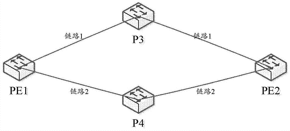
  • Method, PE equipment and system for linear protection switching
  • Method, PE equipment and system for linear protection switching
  • Method, PE equipment and system for linear protection switching

Examples


Embodiment Construction

[0065] In order to make the purpose, technical solution and advantages of the present invention more clear, the embodiments of the present invention will be described in detail below in conjunction with the accompanying drawings. It should be noted that, in the case of no conflict, the embodiments in the present application and the features in the embodiments can be combined arbitrarily with each other.

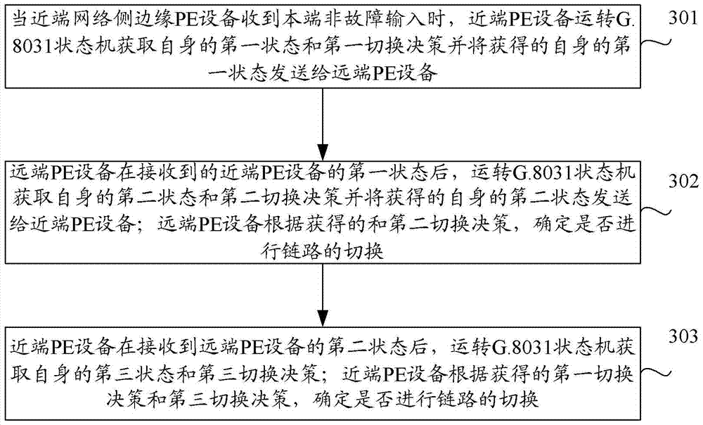
[0066] image 3 It is a flow chart of the method for linear protection switching in the present invention, such as image 3 shown, including:

[0067] Step 301: When the near-end network side edge (PE) device receives the local non-fault input, the near-end PE device operates the G.8031 state machine to obtain its own first state and first switching decision and obtain its own second A status is sent to the remote PE device.

[0068] Further, at this time, the near-end PE device does not perform link switching.

[0069] It should be noted that the near-end PE device can o...


PUM


Abstract

The present invention provides a linear protection switching method, PE equipment and system, including: when the near-end network side edge PE equipment receives the local non-fault input, obtains its own first state and first switching decision and The first state of the remote PE device is sent to the remote PE device; the remote PE device obtains its own second state and second switching decision after receiving the first state of the local PE device, and sends the obtained second state of itself to the near-end PE device; the remote PE device determines whether to switch the link according to the acquired and second switching decisions; the near-end PE device obtains its own third state after receiving the second state of the remote PE device and a third handover decision; the near-end PE device determines whether to perform link handover according to the obtained first handover decision and the third handover decision. The technical solution of the invention enhances the controllability of the network, effectively avoids the problem of timeliness and the problem of service interruption of up to 5s in the process of operating the network.

Description

technical field [0001] The present invention relates to network communication technology, in particular to a linear protection switching method, network side edge (PE, Provider Edge) equipment and system. Background technique [0002] The carrier-level reliability requirements of the communication system include high network reliability requirements, and the services carried by the telecom network must meet the 50ms network failure recovery performance requirement. In order to achieve the service self-healing performance required by the carrier level on the Packet Transport Network (PTN) equipment, ITU-T and other related standard organizations have proposed the G.8031 linear protection switching standard for the Ethernet service. Linear protection switching is a protection mechanism that allocates corresponding protection resources for working resources. It implements network resource switching in a predictable manner, which facilitates network planning, deployment, and man...

Claims


Application Information

Patent Timeline
Patent Type & Authority Patents(China)
IPC IPC(8): H04L12/703H04L12/707H04L45/28H04L45/24
Inventor 邢家茂郭瑞王海龙彭兴文
Owner RAISECOM TECH
Learn More