[0044] 1. System structure
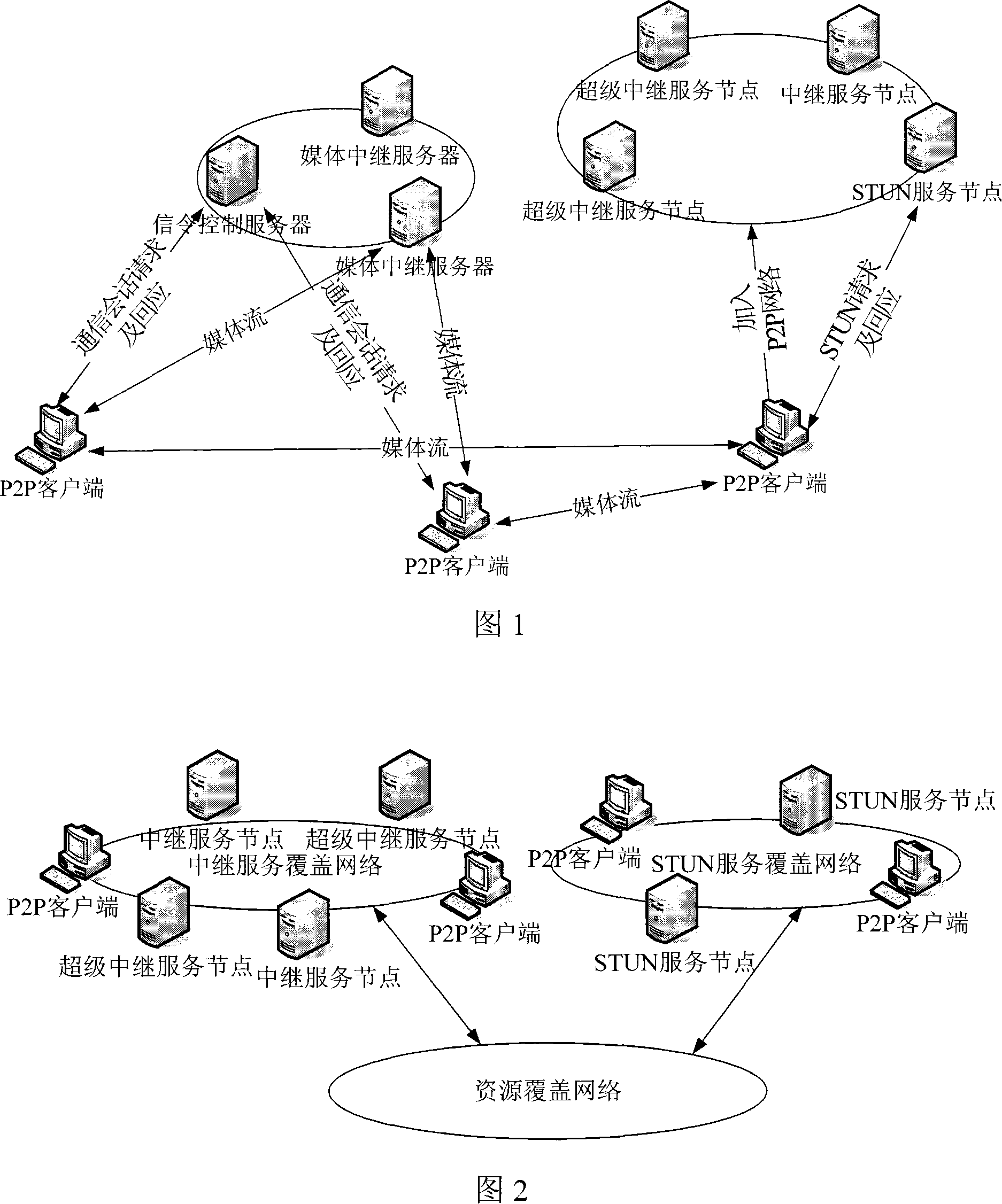
[0045] As shown in Figure 1, the SIP softswitch system supporting P2P media transmission of the present invention includes a signaling control server, a media relay server, a super relay service node, a STUN service node, and a P2P client or ordinary client, using the extended SIP protocol As the communication protocol of the signaling control layer, the signaling control server at the center of the system centrally processes and forwards; media transmission supports media relay server forwarding, point-to-point direct through ICE mode, and multiple paths for P2P network transmission; among them, P2P network transmission The path is optimized in accordance with the established strategy, and finally the communication terminal selects the media transmission path according to the established evaluation mechanism; the media stream transmission adopts an encryption method, and the encryption key is negotiated by the communication parties during the call establishment process. The signaling control process of the session establishment process is fully compatible with the standard SIP protocol, so the system is compatible with all clients that follow the SIP protocol standard, including various soft phones, IP phones, and mobile communication terminals. among them:
[0046] The signaling control server is the control center of the entire IP communication system. All SIP messages are forwarded through the signaling control server; it provides the functions of a standard registration server and proxy server, accepts registration requests from P2P clients or ordinary clients, and Register the registration information in the database of the signaling control server; responsible for the establishment, modification and removal of all multimedia communication sessions; responsible for selecting the media relay server for the communication session, and providing an alternative path for media transmission that is forwarded by the media relay server ;
[0047] The media relay server has a public IP address, processes the relay request from the signaling control server, and allocates a relay port for the communication session. Both the P2P client or the ordinary client send media data packets to the relay port, and the media The relay server forwards the media data packets from one P2P client or ordinary client to another P2P client or ordinary client, and does not perform other additional operations on real-time data, so as to minimize the forwarding delay of real-time data;
[0048] Super relay service node, a long-running relay service node, joins the P2P network as a Bootstrap node of the P2P network; processes relay requests from P2P clients, allocates relay ports for communication sessions, and relays P2P clients Media data packets between;
[0049] STUN service node, joins the P2P network as a Bootstrap node of the P2P network; handles STUN requests from P2P clients, and has standard STUN server functions;
[0050] In addition to fully complying with the standard SIP protocol, the P2P client also supports the encryption processing of media stream data packets, ICE function and P2P function: in the process of establishing communication signaling control interaction, the P2P client negotiates for the media stream A one-time encryption key for data packet encryption; after establishing the communication signaling control interaction, perform an ICE interaction process with another P2P client to find an ICE point-to-point direct media transmission alternative path for this communication; In the P2P network, this communication is looking for alternative media transmission paths forwarded by the relay service node; when it is detected that it meets the conditions of becoming a relay service node, the P2P client applies to join the P2P network to provide other P2P clients with Following the service. With the continuous expansion of the system, there are more and more clients, and at the same time, the number of relay service nodes that provide relay services increases accordingly.
[0051] The signaling control server and the media relay server do not have the P2P function, that is, they do not join the P2P network or obtain resources from the P2P network; the super relay service node and the STUN service node all have the P2P function. To the P2P network, provide corresponding services for communication terminals, and deploy them on stable machines.
[0052] 2. P2P network structure
[0053] As shown in Figure 2, the P2P network has a two-layer structure, namely a resource overlay network and a service overlay network. The resource overlay network provides a unified resource storage and retrieval function for the service overlay network; the service overlay network faces different service types. Each service type forms an independent overlay network, and all service overlay networks use a unified resource overlay network access interface to publish and retrieve service information.
[0054] The service types supported by the P2P network include relay service and STUN service. For relay service, the P2P client needs to find an available relay service node in a short time, and the relay service node is connected to the two communication terminals. The delay should be relatively small. Therefore, it is necessary to fully mine the topology information of the relay service overlay network. The corresponding resource overlay network adopts a complex graph model. Each client node obtains a large amount of service node information from the resource overlay network according to certain strategies. Filter it, and cache part of the available service nodes, and periodically exchange information between the client and the relay service node, and between the relay service node and the relay service node; for STUN services, due to real-time The requirements are not high. The resource overlay network adopts a simple graph model. Each P2P client node obtains STUN service node information from the resource overlay network and caches the available STUN service nodes.
[0055] 3. Protocol hierarchical structure of P2P network constituent entities
[0056] As shown in Fig. 3, the P2P client is divided into SIP application layer, P2P service layer and P2P access layer from top to bottom. The three are relatively independent. The lower layer provides services to its upper layer in the form of a dynamic link library.
[0057] As shown in Figure 4 and Figure 5, the super relay service node and STUN service node are divided into P2P service layer and P2P access layer from top to bottom, which are relatively independent. The lower layer is the upper layer in the form of a dynamic link library. Provide services.
[0058] The SIP application layer completes the control of the extended SIP protocol, interacts with the P2P service layer through interfaces, and completes the access and use of P2P network resources.
[0059] The P2P access layer provides an open and transparent resource overlay network access interface for the P2P service layer, which is shared by all service overlay networks, including the storage and retrieval of service resources in the resource overlay network.
[0060] The P2P service layer abstracts all P2P service types, and the service types are relatively independent. Each service type is divided into service layer client logic and service layer server logic according to different functional roles;
[0061] The service layer client logic provides an interface for the SIP application layer to access service resources. The specific functions include:
[0062] 1) Service node evaluation: test the connectivity, effectiveness and performance of the service node;
[0063] 2) Service node screening: select the service node with better performance according to the established strategy;
[0064] 3) Service node management: Multi-level caching of service nodes, dynamic and efficient management of service nodes;
[0065] 4) Self-evaluation mechanism: Self-evaluation of multiple indicators of the terminal, including NAT type, network bandwidth, CPU capacity and occupancy rate, memory size and utilization rate, etc.; when it is determined that a certain service can be provided, the P2P network is booted as a service node;
[0066] 5) Service resource request: request specific service resources from the service node to provide services for the SIP application layer.
[0067] The service layer server logic provides specific service resources for P2P clients, and the specific functions include:
[0068] 1) Service resource management: Manage and count local service resources, and recover abnormally released service resources to ensure that the resources can be reused, and provide the actual carrying capacity of various services for the service layer client logic;
[0069] 2) Local resource statistics: collect and count the local CPU capacity and occupancy rate, memory size and usage rate, and bandwidth parameters;
[0070] 3) Provide resource services: respond to service resource requests from the client logic of the service layer and provide related services for them.
[0071] 4. System implementation method
[0072] 4.1 Summary of implementation methods
[0073] The implementation method of the SIP soft switch system supporting P2P media transmission of the present invention has the following steps:
[0074] System initialization: Signaling control server, media relay server, super relay service node and STUN service node start and initialize; super relay service node joins the relay service overlay network; STUN service node joins the STUN service overlay network;
[0075] P2P clients and ordinary clients register with the signaling control server; the signaling control server accepts client registration and updates the user information database;
[0076] The P2P client connects to the relay service overlay network and the STUN service overlay network;
[0077] The P2P client conducts self-evaluation, and if it passes the evaluation, it joins the relay service overlay network and becomes a relay service node; the P2P client that becomes the relay service node waits for relay resource requests from other P2P clients and provides relays for it service;
[0078] Clients establish communication sessions through control signaling interaction: The signaling control server processes and forwards control signaling, selects a media relay server for this communication, and provides an alternative path for media transmission that is forwarded by the media relay server; The P2P client determines whether another client has the P2P function according to the control signaling interaction;
[0079] If both communication parties are P2P clients, the P2P client carries ICE to collect address information in the above control signaling interaction, and performs ICE connectivity detection after the control signaling interaction, and looks for ICE point-to-point direct media transmission for this communication Alternative path
[0080] If the ICE connectivity test result is that the LAN point-to-point direct connection is not achieved, the P2P client searches for an alternative media transmission path forwarded by the relay service node for this communication in the relay service overlay network;
[0081] The caller of the P2P client evaluates all the alternative media transmission paths, selects the media transmission path with the best performance, and both parties of the P2P client switch media transmission to the optimal media transmission path;
[0082] After switching to the optimal media transmission path, both P2P clients still retain other alternative media transmission paths and keep alive periodically;
[0083] If the current transmission path fails and the call is interrupted, both parties of the P2P client switch to the alternative media transmission path;
[0084] After the communication session ends, the P2P client releases the P2P network media transmission path; the signaling control server releases the media transmission path forwarded by the media relay server.
[0085] 4.2 Working steps of main functional entities
[0086] 4.2.1 Signaling Control Server
[0087] 1) Initialization, including setting the IP address, port number, etc., and initializing the user information database;
[0088] 2) Waiting for the registration of the client;
[0089] 3) After receiving the client registration, update the user information database;
[0090] 4) Waiting to receive the client's communication request;
[0091] 5) After receiving the communication request from the client, select the media relay server for this communication, modify the communication request, determine the destination and forward the communication request;
[0092] 4.2.2 Media Relay Server
[0093] 1) Initialization, including setting the IP address, port number, etc.;
[0094] 2) Waiting to receive the relay request from the signaling control server;
[0095] 3) Receive the relay request from the signaling control server, assign the relay address and port number for the communication session, and relay the media stream data packets of both parties;
[0096] 4.2.3 Super Relay Service Node
[0097] 1) Initialization, including setting the IP address, port number, etc.;
[0098] 2) Join the relay service coverage network;
[0099] 3) Waiting to process the relay request from the P2P client;
[0100] 4) Receive the relay request from the P2P client, allocate the relay address and port number for the communication session, and relay the media stream data packets of both parties;
[0101] 4.2.4 STUN service node
[0102] 1) Initialization, including setting the IP address, port number, etc.;
[0103] 2) Join the STUN service coverage network;
[0104] 3) Waiting to process STUN request from P2P client
[0105] 4) Receive a STUN request from the P2P client, and respond according to the type of STUN request;
[0106] 4.2.5 P2P client
[0107] 1) Initialization, including setting the IP address, port number, etc.;
[0108] 2) Registration: Use the REGISTER message in the SIP protocol to register with the signaling control server;
[0109] 3) Connect to the relay service overlay network: Obtain multiple relay service nodes from the relay service overlay network, perform performance evaluation, and store them in the cache in order of performance priority;
[0110] 4) Connect to the STUN service overlay network: Obtain multiple STUN service nodes from the STUN service overlay network, perform performance evaluation, and store them in the cache in order of performance priority;
[0111] 5) Self-evaluation: Evaluate whether the P2P client itself meets the conditions of becoming a relay service node, see section 4.3, if the evaluation passes, it will join the relay service overlay network and become a relay service node;
[0112] 6) The P2P client that becomes the relay service node waits to process relay requests from other P2P clients and provides relay services for them;
[0113] 7) Communication session interaction process with another client: use INVITE message, process and forward via signaling control server, see section 4.4;
[0114] 4.3 P2P client self-evaluation mechanism
[0115] The relay service layer client logic of the P2P client performs a self-evaluation process, as shown in Figure 6 and Figure 1, including the following processes:
[0116] Detect multiple indicators of the P2P client itself; including network bandwidth, CPU capacity and occupancy rate, memory size and utilization rate, etc.;
[0117] If the set threshold is met, use STUN service to detect whether the P2P client itself is behind NAT;
[0118] If it is behind NAT, use STUN service to determine the type of NAT;
[0119] If the type of NAT is Full Cone NAT, the P2P client becomes a relay service node and joins the relay service overlay network;
[0120] Or if the result of using the STUN service to detect whether the P2P client itself is behind the NAT is not behind the NAT, the P2P client becomes a relay service node and joins the relay service overlay network.
[0121] 4.4 Communication session interaction process
[0122] As shown in Figure 7, taking the communication session interaction process between the P2P client UA-1 and the P2P client UA-2 as an example, the steps are as follows:
[0123] 1) The P2P client calling party UA-1 and the P2P client called party UA-2 complete the session establishment process through the interaction of the control signaling INVITE/200OK/ACK message:
[0124] After the signaling control server receives the INVITE message, it selects a media relay server for this session. After receiving the INVITE message and the 200OK message, it sends a relay request to the selected media relay server; the media relay server allocates it Relay port, and put the relay address and port information in the relay response and send it back to the signaling control server; the signaling control server modifies the media stream address and port information of the SDP part of the INVITE message and 200OK message according to the relay response, and forwards it INVITE message and 200OK message;
[0125] The P2P client calling party UA-1 sets the "i=" parameter in the SDP part of the INVITE message to "sipp2p"; the P2P client called party UA-2 sets the "i=" parameter in the SDP part of the 200OK message to "sipp2p" "; The P2P client calling party UA-1 and the P2P client called party UA-2 know that the communication peer has the P2P function by checking whether the "i=" parameter in the SDP part of the INVITE/200OK message is "sipp2p".
[0126]2) The P2P client calling party UA-1 and the P2P client called party UA-2 carry the address information collected by ICE in the SDP part of the INVITE and 200OK messages respectively, and perform ICE connectivity detection after the control signaling exchange; The address information collected by ICE includes from high to low priority:
[0127] Local address and port for sending and receiving media streams;
[0128] If the local address for sending and receiving media streams is a private network address, it also includes the NAT-mapped address obtained through the STUN protocol.
[0129] 3) After the ICE connectivity test, the P2P client calling party UA-1 and the P2P client called party UA-2 did not realize the direct connection between the LAN and the relay service coverage network for this communication. Alternative media transmission path forwarded by the service node
[0130] 4) The P2P client calling party UA-1 evaluates all alternative paths, sends a test data stream for a predetermined time to the alternative path, calculates the packet loss rate, delay, and jitter of the test data stream, and finally chooses P2P network transmission path, P2P client calling party UA-1 and P2P client called party UA-2 switch media and transmit to the relay service node;
[0131] 5) After the media transmission path is selected, the P2P client calling party UA-1 and the P2P client called party UA-2 still retain other alternative transmission paths and keep them alive periodically. Once the current transmission path fails As a result, the call is interrupted, and it can be switched to an alternative media transmission path in time;
[0132] 6) The P2P client calling party UA-1 ends the communication session, sends a BYE message to the signaling control server, and sends a relay resource recovery request to the relay service node in the P2P network transmission path, requesting the relay service node to recycle Relay resources: After receiving the BYE message, the signaling control server sends a teardown request to the media relay server selected for this session, requesting the media relay server to reclaim the relay resources, and forward the BYE message to the called party of the P2P client UA-2, the called party UA-2 of the P2P client responds to the BYE message.
[0133] 4.5 The selection process of P2P network transmission path
[0134] As shown in Figure 8, the P2P client searches for an alternative media transmission path forwarded by the relay service node for this communication in the relay service overlay network, where P2P clients use INFO messages to interact, the steps are as follows :
[0135] 1) The SIP application layer of the calling party UA-1 of the P2P client requests the currently available relay service node from the P2P service layer. The P2P service layer selects multiple relay service nodes according to priority from the relay service node cache list to form a new one The list is sorted in ascending order according to the comprehensive evaluation value and returned to the SIP application layer;
[0136] 2) The SIP application layer of the calling party UA-1 of the P2P client constructs the first INFO message INFO-1, fills the obtained relay service node information into the message body of the message, and sends the message to the P2P client Calling party UA-2;
[0137] 3) After the SIP application layer of the called party UA-2 of the P2P client receives the first INFO message INFO-1, it sends back a response message 200 OK to the calling party of the P2P client, and sends the message from the first INFO message INFO-1 to the P2P client. The message body part obtains the list information of the relay service node to be selected;
[0138] 4) The SIP application layer of the called party UA-2 of the P2P client requests the P2P service layer to comprehensively evaluate all the relay service nodes in the relay service node list, and compare the obtained delay value with the delay of the calling party of the P2P client The value is added as the new delay value of the service node, which is reordered according to the priority delay value;
[0139] 5) The SIP application layer of the called party UA-2 of the P2P client constructs the second INFO message INFO-2, fills the new relay service node list information into the message body of the message, and sends the message to the P2P client Calling party UA-1;
[0140] 6) After the SIP application layer of the calling party UA-1 of the P2P client receives the INFO-2 message, it sends a response message 200 OK to the called party of the P2P client, and obtains it from the message body of the second INFO message INFO-2 List information of relay service nodes evaluated by both P2P clients;
[0141] 7) The SIP application layer of the calling party UA-1 of the P2P client obtains the first relay service node in the above relay service node list, and requests the P2P service layer to request relay resources from the relay service node; if the request is successful , Construct the third INFO message INFO-3, fill in the obtained relay resource information (including the IP address of the relay service node, service control port, media relay port, etc.) into the message body of the message, and send the When the message reaches the called party UA-2 of the P2P client, go to step 8);
[0142] If the request is unsuccessful, delete the relay service node from the relay service node list and repeat step 7); if the relay service node list is empty, the selection process of the P2P network transmission path fails. After a period of time, Restart the selection process of the P2P network transmission path;
[0143] 8) After the SIP application layer of the called party UA-2 of the P2P client receives the third INFO message INFO-3, it sends a response message 200 OK to the calling party of the P2P client, and receives the message from the third INFO message INFO-3. The message body part obtains the information of the relay service node to be selected, and requests the relay resource from the relay service node. If the request is successful, the fourth INFO message INFO-4 is constructed, and the obtained relay resource information (including the middle After the service node's IP address, service control port, media relay port, etc.) fill in the message body of the fourth INFO message INFO-4, send the fourth INFO message INFO-4 to the P2P client caller; if The request is unsuccessful, and the called party UA-2 of the P2P client does not perform any operation;
[0144] 9) After the SIP application layer of the calling party UA-1 of the P2P client receives the fourth INFO message INFO-4, it sends back a response message 200 OK to the called party of the P2P client, and receives the fourth INFO message from the INFO-4. The message body part obtains the information of the candidate relay service node; if the fourth INFO message INFO-4 from the called party of the P2P client is not received within a certain period of time, the candidate relay service node is removed from the relay service node Delete from the list, repeat step 7).
[0145] 4.6 Secure transmission of media streams
[0146] A one-time encryption key is used between P2P clients to encrypt the media stream data packets of the communication session. As shown in Figure 9, during the establishment of a communication session, the secure transmission of a one-time encryption key between P2P clients is as follows:
[0147] 1) The caller of the P2P client generates the one-time encryption key (p) for the encrypted media stream data packet of this communication, and uses the user password (sa) of the calling SIP URI as the symmetric key to perform the one-time encryption key Encrypt, and extend the private header field in the INVITE message to carry the encrypted one-time encryption key ((p)sa) and integrity verification information (MD5(p));
[0148] 2) The signaling control server obtains the encrypted one-time encryption key from the INVITE message, decrypts it with the user password (sa) of the calling SIP URI (((p)sa)sa), and then uses the called SIP The user password (sb) of the URI encrypts the decrypted one-time encryption key, and puts the newly encrypted one-time encryption key ((p)sb) back into the INVITE message and forwards it to the called party on the P2P client ;
[0149] 3) The called party of the P2P client obtains the encrypted one-time encryption key and integrity verification information from the INVITE message, and uses the user password (sb) of the called SIP URI to decrypt the encrypted one-time encryption key ( ((p)sb)sb), get a one-time encryption key, and perform integrity verification.