


Quick Research
Generate reliable direction feasibility study reports for your R&D in just a few steps.

Technical Q&A
Discover and master advanced knowledge NOW. Basics, ideas, possibilities, all at once.

Find Solutions
As an expert in R&D theories, this can generate solutions to your technical problems instantly.

Evaluate Feasibility
Analyze your overall solution with one click, know your potential R&D risks in advance.

Monitor Landscape
Get weekly tech updates, stay abreast of the latest tech innovations and key insights.
Neighbor cell transmission parameter configuration method, determination method thereof and associated device
A technology for transmission parameters and neighboring cells, which is applied in network data management, wireless communication, electrical components, etc., and can solve problems such as inability to guarantee, increased reception complexity, and excessive waste of CSS resources.
- Summary
- Abstract
- Description
- Claims
- Application Information
AI Technical Summary
Problems solved by technology
Method used
Image

Examples
Embodiment 1
[0152] According to the background technology, in the traditional MBSFN subframe configuration, the indication of the MBSFN subframe does not distinguish which subframes are used for PMCH and which subframes are used for PDSCH transmission, resulting in the existence of vague question. In order to solve this problem, 2 ways are considered here:
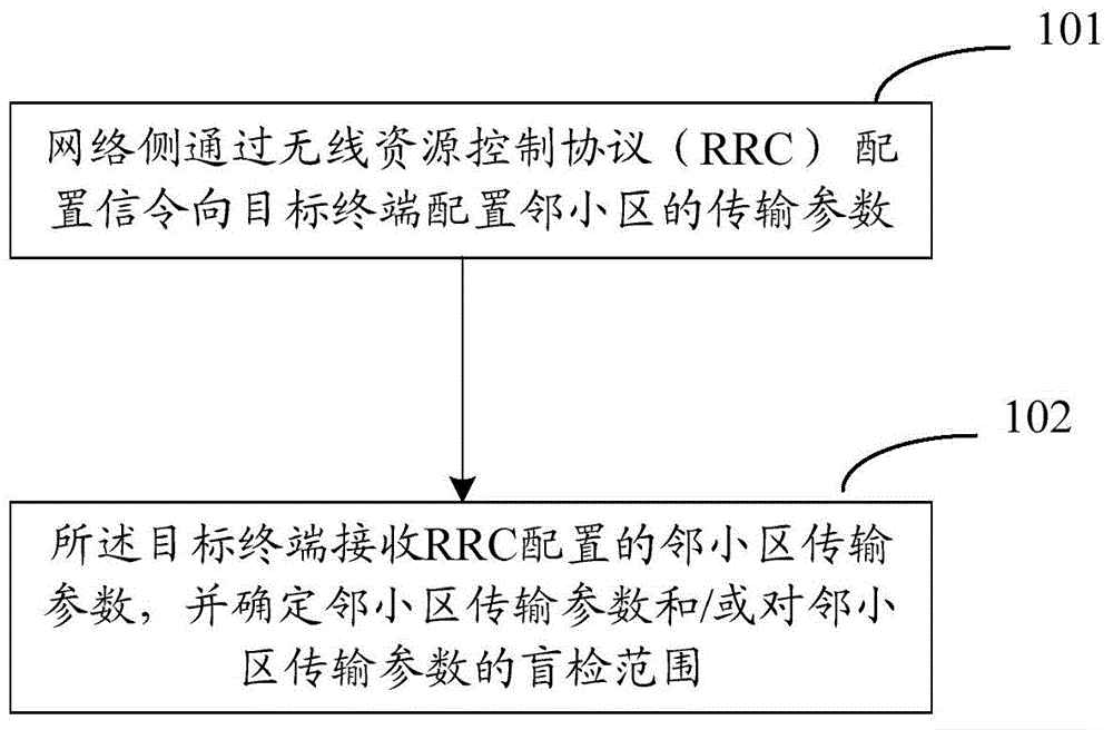
[0153] Mode 1: The high layer configures the MBSFN subframe potentially assigned to the PMCH or PDSCH transmission by the neighboring cell through RRC signaling; the terminal receives the MBSFN subframe configuration parameters; and performs interference cancellation processing based on the configuration parameters, specifically,
[0154] If the subframe in which the terminal receives the target PDSCH signal is included in the subframe indicated by the MBSFN subframe configuration parameter, the terminal does not perform interference cancellation processing, or performs PMCH interference cancellation based on the MBSFN reference signal ...
Embodiment 2
[0164] In this embodiment, different transmission modes are classified, and classification information is indicated to the terminal. Specifically, the network side and the terminal classify the transmission modes supported by the current protocol according to a pre-agreed manner, and the network side configures a subset of transmission modes allowed on different resource units, or a subset of restricted transmission modes.
[0165] Method 1: Divide the transmission modes into three categories: TM type1, TM type2, and TM type3. The network side classifies the transmission modes into the above three categories according to the characteristics of different transmission modes. The classification method can be as follows:
[0166] TM type1 corresponds to transmission mode {TM3with rank>1, TM7}, TM type2 corresponds to transmission mode {TM1, TM2, TM4, TM3with rank=1, TM5, TM6}, TM type3 corresponds to transmission mode {TM8, TM9, TM10 };
[0167] Or TM type1 corresponds to {TM3with...
Embodiment 3
[0189] Based on the TM type parameter configuration method described in Embodiment 2, in this embodiment, it is further considered to configure other parameters based on the TM type configuration parameter, so as to further reduce signaling overhead.
[0190] According to the grouping method of TM types in embodiment 2 and the difference of transmission parameters between different TM types, the basic idea of this embodiment is based on the resource locations corresponding to different TM types in the high-level configuration parameters of TM type (including the corresponding time domain, frequency domain resource location), respectively configure the blind detection parameter limit set at the resource location corresponding to different TM types. For example, taking method 2 in Embodiment 2 as an example, for resource positions corresponding to TM type1 (which can be resource units, resource blocks, subframes, time slots or a combination of resource units / resource blocks and...
PUM
 Abstract
Description
Claims
Application Information
 - R&D Engineer
- R&D Manager
- IP Professional
- Industry Leading Data Capabilities
- Powerful AI technology
- Patent DNA Extraction
Browse by: Latest US Patents, China's latest patents, Technical Efficacy Thesaurus, Application Domain, Technology Topic, Popular Technical Reports.
© 2024 PatSnap. All rights reserved.Legal|Privacy policy|Modern Slavery Act Transparency Statement|Sitemap|About US| Contact US: help@patsnap.com