Supercharge Your Innovation With Domain-Expert AI Agents!

Injection mold with hot runner distributor

一种注塑模具、热流道的技术,应用在具有热流道分配器的注塑模具领域

Active Publication Date: 2017-03-08
FOSTAG FORMENBAU
View PDF9 Cites 0 Cited by
  • Summary
  • Abstract
  • Description
  • Claims
  • Application Information

AI Technical Summary

Problems solved by technology

[0005] Although injection molds with hot runner inlet pipes are shown in various patent documents (such as GB 1299094 or DE 102008045701-A or EP 2263845 B), these patent documents all have other problems, for example, in order to reduce deposits The formation of the hot runner input pipe for the implementation of special material supply

Method used


Image

  • Injection mold with hot runner distributor
  • Injection mold with hot runner distributor

Examples


Embodiment Construction

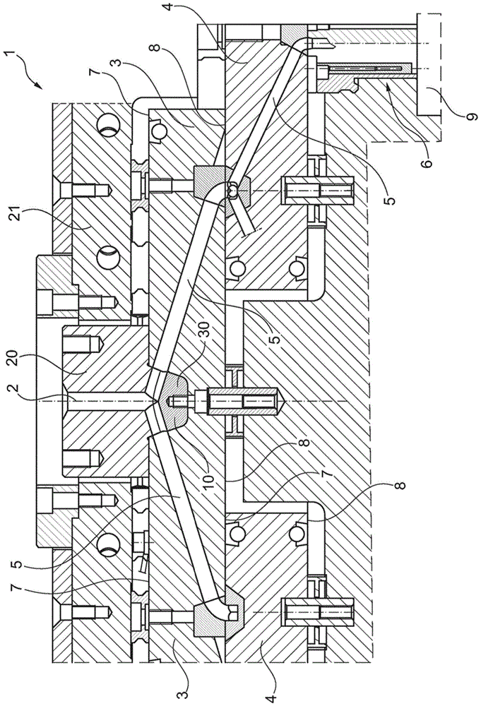
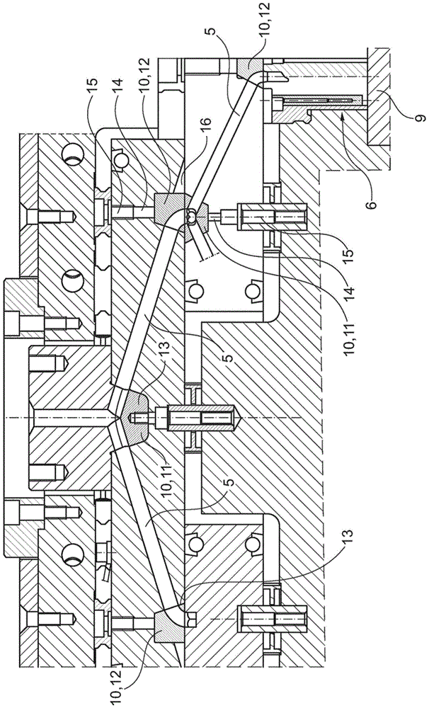
[0011] figure 1 and figure 2 A cross-sectional view of an injection mold according to the invention is shown. The injection mold is denoted by 1 as a whole. At the top, the central supply line 2 can be seen, which is molded in a casting bushing 20 . The casting bushing 20 is held in a fixing plate 21 . Resting against the upper plate 3 is a casting bushing 20 with a central feed line 2 , which is connected to an injection molding device of an extruder or injection molding machine (not shown here). The upper plate is placed flat on the lower plate 4 again. The individual plates are releasably connected to one another by means not discussed further here.

[0012] Heating means are provided in each plate. These heating means may be electrically insulating heating rods or heating channels through which a heating fluid is pumped. Since these heating elements are conventional elements and their configuration is not relevant to the invention, no further description will be gi...


PUM


Abstract

To simplify the cleaning of hot runner feed lines, and consequently to reduce the downtimes, an injection mold with at least one central feed line and a number of plates arranged one above the other is proposed. The injection mold has at least one hot runner feed line with one or more branching points, at which the hot runner feed line changes direction and / or is divided. In each plate, the hot runner feed line runs in a straight line from the upper surface of a plate to the lower surface of the plate. These hot runner feed lines run straight and at an angle within the plate. At least on one side, the hot runner feed lines open out into exchangeable inserts. For cleaning the injection mold, the exchangeable inserts can be removed from the plates and cleaned separately, while the straight-running hot runner feed lines can be mechanically cleaned in a conventional way.

Description

technical field [0001] The invention relates to an injection mold with at least one central supply duct, comprising one or more plates arranged one above the other and at least one hot runner feed with one or more branching points , the hot-runner supply line changes direction and / or distributes at these branch points in order to supply the hot injection molding material (Spritzgussmasse) to two or more chambers. Background technique [0002] Injection molds are molds used to make plastic parts. The injection molding tool is installed in the injection molding machine, where the injection molding material is heated and conveyed in the molten state via so-called hot runner inlets into the chambers, where the corresponding plastic parts are formed. In order to solidify the liquid plastic (plastic), in the region of the cavity, cooling ducts for cooling the region surrounding the cavity run in the injection mold. [0003] Injection molds must be serviced regularly because some...

Claims


Application Information

Patent Timeline
Patent Type & Authority Patents(China)
IPC IPC(8): B29C45/27
CPCB29C45/2725B29C45/2727B29C2045/273B29C2045/2733B29K2905/00B29K2909/02
Inventor 罗尔夫·米勒曼
Owner FOSTAG FORMENBAU
Features
  • R&D
  • Intellectual Property
  • Life Sciences
  • Materials
  • Tech Scout
  • Unparalleled Data Quality
  • Higher Quality Content
  • 60% Fewer Hallucinations
Learn More