Centrifugal force pendulum device, and drive train of motor vehicle

A technology of centrifugal pendulum and vibration-absorbing equipment, which is applied in the field of power transmission

Active Publication Date: 2015-09-23
AUDI AG
View PDF6 Cites 0 Cited by
  • Summary
  • Abstract
  • Description
  • Claims
  • Application Information

AI Technical Summary

Problems solved by technology

This often results in unwanted noise formation

Method used


Image

  • Centrifugal force pendulum device, and drive train of motor vehicle
  • Centrifugal force pendulum device, and drive train of motor vehicle
  • Centrifugal force pendulum device, and drive train of motor vehicle

Examples


Embodiment Construction

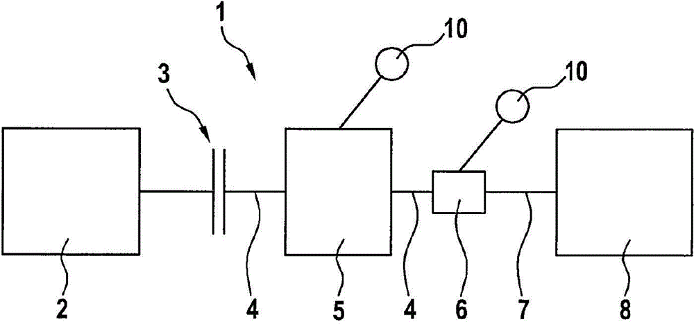
[0025] figure 1 A drive train 1 of a motor vehicle is shown schematically. The drive train has a drive device 2 , which in the exemplary embodiment presented here is an internal combustion engine. The drive device 2 is operatively or operatively connected via a separating clutch 3 to a shaft 4 of a further drive device 5 , for example an electric motor. On the side of the other drive 5 facing away from the separating clutch 3 , the shaft 4 is connected to a transmission 6 , in particular a transmission. The shaft 4 thus appears as a transmission input shaft on the side of the drive 5 facing the transmission 6 . The transmission output shaft 7 is operatively connected to at least one wheel, not shown here, of a chassis 8 of the motor vehicle. It is obvious that the torque applied to the wheels and thus the driving of the motor vehicle can be carried out either only by means of the other drive device 5 or by engaging the separating clutch 3 by means of the drive device 2 and ...


PUM


Abstract

The invention relates to a centrifugal force pendulum device (10), comprising a pendulum mass carrier (11) that can be rotated about an axis of rotation (15) and at least one pendulum mass (12), which is supported on the pendulum mass carrier (11) in such a way that the pendulum mass (12) can be moved along a track (18) between two end stops (19, 20) that are arranged at a distance from each other in the circumferential direction with respect to the axis of rotation (15). A spring device (23) is provided, which is designed to push the pendulum mass (12) into one of the end stops (19, 20) when the rotational speed of the pendulum mass carrier (11) about the axis of rotation (15) is below a rotational speed limit. The invention further relates to a drive train (1) of a motor vehicle.

Description

technical field [0001] The invention relates to a centrifugal pendulum type vibration damping device, which has a pendulum mass support capable of rotating around a rotating shaft and at least one pendulum mass, the pendulum mass supported so as to be able to rest on the pendulum mass support along a working track Movement between two end stops on the shaft, said two end stops being circumferentially spaced from each other with reference to the rotation axis. The invention also relates to a drive train of a motor vehicle. Background technique [0002] Centrifugal pendulum dampers of this type are used, for example, in drive trains of motor vehicles in order to at least partially, preferably completely, absorb rotational vibrations induced by the drive of the drive train, in particular the internal combustion engine. Therefore, a centrifugal pendulum damper is used as a shock absorber. Unlike other dampers, the centrifugal pendulum damper can be tuned to defined orders over...

Claims


Application Information

Patent Timeline
Patent Type & Authority Applications(China)
IPC IPC(8): F16F15/14
CPCF16F15/145
Inventor H·迈尔S·舒尔茨
Owner AUDI AG
Why Eureka
Try Eureka