Compact-structure multifunctional robot

A compact, multi-purpose technology, used in manipulators, program-controlled manipulators, metal processing machinery parts, etc., can solve the problems of high cost and complex movement, and achieve the effect of low cost, less freedom, and easy maintenance.

Inactive Publication Date: 2015-09-30
FOSHAN XINHENGCUI MATERIAL TECH CO LTD
View PDF9 Cites 10 Cited by
  • Summary
  • Abstract
  • Description
  • Claims
  • Application Information

AI Technical Summary

Problems solved by technology

[0003] However, for workpiece-like objects, these two types of general-purpose motion platforms have the following disadvantages: first, the movement of the entire week is complex, requiring more than three degrees of freedom to be linked to complete; second, these two types of motion platforms use spatial coord

Method used


Image

  • Compact-structure multifunctional robot
  • Compact-structure multifunctional robot
  • Compact-structure multifunctional robot

Examples


Embodiment 1

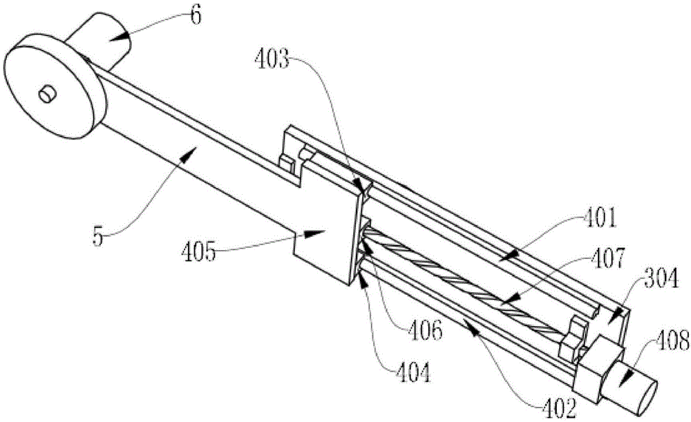
[0050] like image 3 As shown, the telescopic mechanism includes an upper guide rail 401, a lower guide rail 402, an upper slider 403, a lower slider 404, a working head base 405, a nut 406, a screw 407 and a screw power mechanism 408; The upper guide rail 401 and the lower guide rail 402 are installed on the telescopic arm base 304, the upper slider 403 and the lower slider 404 slide along the upper guide rail 401 and the lower guide rail 402 respectively, and the The working head base 405 is fixedly installed on the upper slider 403 and the lower slider 404 at the same time, and the nut 406 is fixedly installed on the working head base 405 and threadedly matched with the screw rod 407. The rod power mechanism 408 is installed on the telescopic arm base 304 and drives the screw rod 407 to rotate, and the working arm 5 is installed on the working head base 405 .

[0051] In this embodiment, the screw power mechanism 408 provides power to drive the screw 407 to rotate. After t...

Embodiment 2

[0054] like Figure 4 As shown, the telescopic mechanism includes an upper rail 411, a lower rail 412, an upper slider 413, a lower slider 414, a working head base 405, a connecting block 416, a telescopic belt 417, a telescopic belt power mechanism 418 and Telescopic pulley 419; the upper side track 411 and the lower side track 412 are installed on the telescopic arm base 304, and the upper side slider 413 and the lower side slider 414 slide on the upper side track 411 and the lower side respectively Track 412, the working head base 405 is installed on the upper slider 413 and the lower slider 414 at the same time, the working head base 405 is fixedly connected with the telescopic belt 417 through the connecting block 416, so The telescopic belt 417 is sleeved on the telescopic pulley 419 and driven by the telescopic belt power mechanism 418 to drive the working head base 405 .

[0055] The working head base 405 is fixedly connected with the telescopic belt 417 through the c...

Embodiment 3

[0057] like Figure 5 As shown, the telescopic mechanism includes an upper rail 411, a lower rail 412, an upper slider 413, a lower slider 414, a working head base 405, a telescopic rack 426, a telescopic gear 427 and a telescopic gear power mechanism 428 The upper rail 411 and the lower rail 412 are mounted on the telescopic arm base 304, the upper slider 413 and the lower slider 414 slide on the upper rail 411 and the lower rail 412 respectively, The working head base 405 is installed on the upper slider 413 and the lower slider 414 at the same time, the telescopic gear 427 and the telescopic gear power mechanism 428 are installed on the telescopic arm base 304, and the telescopic rack 426 is fixedly installed on the working head base 405 , and the telescopic gear 427 meshes with the telescopic rack 426 .

[0058] The telescopic transmission mode of the working arm 5 is rack and pinion transmission, and the transmission is accurate. Wherein, the working head base 405 is fi...


PUM


Abstract

The invention discloses a compact-structure multifunctional robot. The compact-structure multifunctional robot comprises an installation base, an arc-shaped planar rail, an arc-shaped rack, a rack driving mechanism, a stretchable mechanism, a working arm and a working head. The working head is arranged at one end of the working arm. The arc-shaped planar rail is sleeved with the installation base, is matched with the installation base through a sliding pair or a rolling pair and is in an arc shape with the curved and non-closed center line. The arc-shaped rack is fixedly installed on the arc-shaped planar rail. Teeth of the arc-shaped rack can be installed towards the inner side or the outer side of the arc-shaped planar rail. The working arm is arranged at the tail end of the arc-shaped rack. The working head can be stretched under the driving of the stretchable mechanism. Before operation is carried out, a user only needs to know the position of the center line of a pipe and does not need to know the accurate position of the contour of the pipe, and the compact-structure multifunctional robot has the advantages that the freedom degree required by achieving operation movement around the whole circumference of the pipe is small, the manufacturing cost is low, and use and maintaining are convenient.

Description

technical field [0001] The invention relates to the technical field of mechanical processing, in particular to a multipurpose robot with compact structure. Background technique [0002] With the development of automation equipment and robot technology, various coordinate machine tools, machining centers and articulated industrial robots have come out one after another, and gradually formed two types of general motion platforms, coordinate type and articulated type, and the connections at the ends of these two types of motion platforms are different. The job head can complete various job tasks. [0003] However, for workpiece-like objects, these two types of general-purpose motion platforms have the following disadvantages: first, the movement of the entire week is complex, requiring more than three degrees of freedom to be linked to complete; second, these two types of motion platforms use spatial coordinate data To drive the work head to work, it is necessary to know the p...

Claims


Application Information

Patent Timeline
IPC IPC(8): B25J9/08B23Q3/00
Inventor 马道平潘存云张佐江
Owner FOSHAN XINHENGCUI MATERIAL TECH CO LTD
Why Eureka
Try Eureka