Printing apparatus and control program for printing apparatus

A technology for printing devices and recording media, applied in the directions of printing devices, printing, etc., can solve problems such as wiring noise, and achieve the effect of reducing the possibility of noise generation, preventing the deterioration of printing quality, and reducing the possibility of excessive or insufficient power generation.

Active Publication Date: 2015-09-30
SEIKO EPSON CORP
View PDF7 Cites 8 Cited by
  • Summary
  • Abstract
  • Description
  • Claims
  • Application Information

AI Technical Summary

Problems solved by technology

In addition, since the head unit requires a large amount of electric power, when the position of the wiring for supplying such a large electric power changes greatly, noise may be generated from the wiring, and the noise may be propagated to various parts of the printing apparatus.

Method used


Image

  • Printing apparatus and control program for printing apparatus
  • Printing apparatus and control program for printing apparatus
  • Printing apparatus and control program for printing apparatus

Examples


Deformed example 1

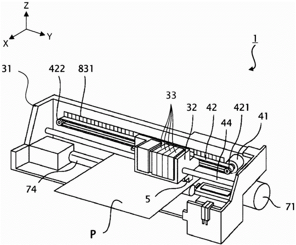
[0237] In the above-mentioned embodiment, both the conductor 21 and the conductor 23 are provided on the lower side of the carriage 32, and on the opposite side of the transport path of the recording medium P when viewed from the carriage 32, but the present invention does not Limited to this aspect, one of the conductor 21 or the conductor 23 may be provided on the frame body 31 or the carriage guide shaft 44 . For example, if Figure 19 As shown, when the conductor 23 is provided on the frame body 31 or the carriage guide shaft 44 , the conductor 24 may be provided at a position facing the conductor 23 on the carriage 32 .

Deformed example 2

[0239] In the above-mentioned embodiments and modified examples, the power transmission unit 2 has the coupling capacitor CM1 on the power supply path and the coupling capacitor CM2 on the discharge path, but the present invention is not limited to this mode, and may only have the coupling capacitor CM1 or the coupling capacitor CM2. One side of capacitor CM2. For example, if Figure 20 As shown, the power transmission unit 2 may have a discharge path set at the ground potential and have a coupling capacitor CM1 only in the power supply path. exist Figure 20 In the example shown, for example, the potential of the carriage guide shaft 44 is set to the ground potential, and the terminal TE32 of the head unit 5 (refer to Figure 8 ) is electrically connected to the carriage guide shaft 44, so that the discharge path can be set to the ground potential. In addition, in Figure 20 In the example shown, the driving method of the power supply path is the same as that of the above...

Deformed example 3

[0241] In the above-mentioned embodiments and modified examples, the power transmission unit 2 transmits power via coupling capacitors (coupling capacitor CM1, coupling capacitor CM2), but the present invention is not limited to this method, and the power transmission unit 2 may also transmit power via at least two conductors. Electromagnetic coupling to transmit electricity.

[0242] For example, an inductance may be used as the conductor 21 and the conductor 22 , and electric power may be transmitted by mutual induction between the conductor 21 and the conductor 22 . In this case, the power supply unit 10 may output the power supply Ws and the power supply voltage VS of a magnitude corresponding to the type of the recording medium P to the power transmission unit 2 . More specifically, the power supply unit 10 may output the supply power Ws and the power supply voltage VS having a magnitude corresponding to the magnetic permeability of the recording medium P to the power tra...


PUM


Abstract

Provided is a printing apparatus including: a head unit that is provided with a discharge unit which discharges a liquid; a carriage into which the head unit is built; a power delivery unit that delivers at least a part of supplied power to the head unit; and a power supply unit that supplies power to the power delivery unit, in which the power delivery unit is provided with a first conductor and a second conductor, wherein power that is supplied from the power supply unit is delivered to the head unit through a coupling capacitance that is formed by the first conductor and the second conductor, and in which the power supply unit supplies different amounts of power to the power delivery unit depending on a type of a recording medium that is in a transport pathway.

Description

technical field [0001] The present invention relates to a printing device and a control program for the printing device. Background technique [0002] In a printing device such as an inkjet printer, a configuration in which a head unit including a discharge unit that discharges ink and a drive circuit that drives the discharge unit is mounted on a carriage that is movable relative to the main body of the printing device is known. In such a printing device, in order to supply electric power to a head unit mounted on a carriage, a structure in which the main body of the printing device and the carriage are physically connected by wiring is common. [0003] Specifically, there is known a method of using FFC (Flexible Flat Cable: flexible flat cable) as wiring for power supply to the head unit, or using a timing belt connected to the carriage to move the carriage (for example, Patent Document 1). . [0004] Patent Document 1: JP Unexamined Publication No. 2011-46118 [0005] ...

Claims


Application Information

Patent Timeline
Patent Type & Authority Applications(China)
IPC IPC(8): B41J2/01B41J29/393
CPCB41J13/0009B41J23/00B41J11/0035
Inventor 大塚修司野村勋臼田秀范松山彻
Owner SEIKO EPSON CORP
Why Eureka
Try Eureka