
A Fault Correction Device and Method Based on Data Flow Driven Computation

A technology of a correction device and a correction method, which is applied in the directions of calculation, redundancy in hardware, error detection of data, and electrical digital data processing, etc. The effect of improving the processing speed and reducing the probability of interruption

Active Publication Date: 2021-12-31
HEFEI UNIV OF TECH
View PDF0 Cites 0 Cited by
  • Summary
  • Abstract
  • Description
  • Claims
  • Application Information

AI Technical Summary

Problems solved by technology

The resource consumption of this method is half that of the hardware three-mode redundancy method, but the processing speed of the calculation will be greatly reduced, and with the increase of the probability of single event flipping, the probability of data flow-driven calculation being interrupted will be relatively high

Method used


Image

  • A Fault Correction Device and Method Based on Data Flow Driven Computation
  • A Fault Correction Device and Method Based on Data Flow Driven Computation
  • A Fault Correction Device and Method Based on Data Flow Driven Computation

Examples


Embodiment 1

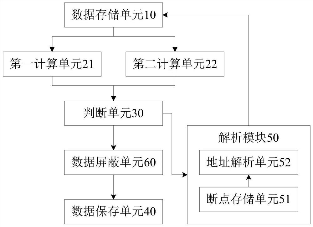
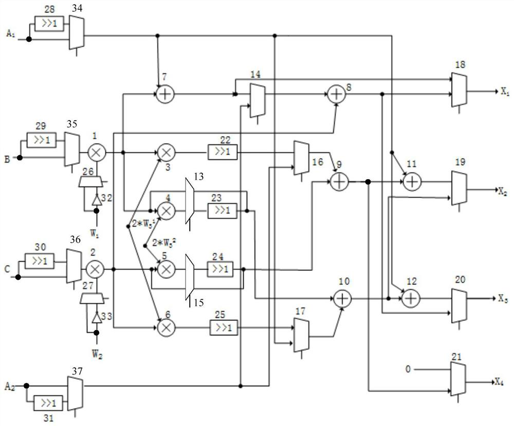
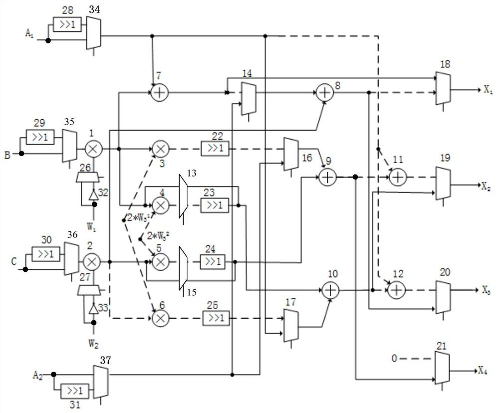
[0029] Combine below Figure 1 to Figure 5 The failure correction device in this embodiment will be described.

[0030] like figure 1 As shown, a fault correction device based on data stream-driven calculation in this embodiment includes: a data storage unit 10, two calculation units, a judgment unit 30, a data storage unit 40 and an analysis module 50; the data storage unit 10 is arranged in The input end of the fault correction device, the data storage unit 10 is used for simultaneously sending the corresponding original data to the two computing units according to the data address;

[0031] Specifically, the data storage unit 10 is composed of a plurality of random access memories (RAMs), and is driven by data addresses to send original data to the two computing units, that is, data is stored in the data storage unit 10 list, the data storage unit 10 retrieves the original data corresponding to the data address according to the data address in the data list, and then send...

Embodiment 2

[0078] Combine below Figure 6 to Figure 7 The fault correction method in this embodiment will be described.

[0079] like Image 6 As shown, a fault correction method based on data flow-driven calculation in this embodiment includes:

[0080] Step S10, according to the data address, the original data is calculated by two identical calculation units, and the first calculation result and the second calculation result are obtained respectively;

[0081] Specifically, according to the received calculation instruction, a crossbar matrix control instruction is generated, and a calculation unit conforming to the calculation instruction is controlled to be generated, thereby realizing the calculation of the original data, and obtaining the first calculation result and the second calculation result.

[0082] Step S20, judging whether the first calculation result is equal to the second calculation result, when it is judged to be yes, go to step S30, and when it is judged to be no, go...


PUM


Abstract

The present application discloses a fault correction device and method based on data flow-driven calculation. The device includes: a data storage unit is set at the input end of the fault correction device, and is used to send original data to two calculation units at the same time according to the data address; The unit is used to perform mirror calculation on the original data; the judging unit is used to send the mirror calculation result to the data storage unit when it is judged that the two mirror calculation results are equal; when it is judged that the two mirror calculation results are not equal, generate and send a fault Point the address to the analysis module; the data storage unit is used to generate a storage address according to the data address, and store the mirror calculation result according to the storage address; the analysis module is used to obtain the data address according to the fault breakpoint address, and send it to the data storage unit. Through the technical solution in the application, it is beneficial to reduce the time consumption of the chip data flow-driven calculation, reduce the resource consumption of the chip, and reduce the interruption probability of the data flow-driven calculation.

Description

technical field [0001] The present application relates to the technical field of chip computing, and in particular, to a fault correction device based on data flow-driven calculation and a fault correction method based on data flow-driven calculation. Background technique [0002] Cosmic rays, composed of multiple ray nuclei and a single heavy ion, are extremely penetrating and can cause great damage to electronic systems. Single particle flip is one of the main reasons for the failure and abnormal operation of the electronic system in the space environment. The existing mainstream hardware accelerators generally use the data stream-driven computing mode. Because in the high altitude or even outer space environment, the phenomenon of electronic components in the chip caused by single particle flip often occurs, which affects the correctness of the chip calculation results. Therefore, it is necessary to perform fault detection and correction on the operation result data of t...

Claims


Application Information

Patent Timeline
Patent Type & Authority Patents(China)
IPC IPC(8): G06F11/16
CPCG06F11/1641G06F11/165
Inventor 宋宇鲲项阳孙晓霞
Owner HEFEI UNIV OF TECH
Learn More