Energy storage cabin air duct system and energy storage cabin with air duct system

An air duct and energy storage technology, which is applied in the field of energy storage cabins and electric energy storage cabins, can solve problems such as unbalanced air velocity at the air supply outlet, and achieve the effect of ensuring performance and temperature control effects

Active Publication Date: 2015-09-30
XJ ELECTRIC +2
View PDF12 Cites 2 Cited by
  • Summary
  • Abstract
  • Description
  • Claims
  • Application Information

AI Technical Summary

Problems solved by technology

[0004] The purpose of the present invention is to provide an energy storage cabin air duct system to solve the problem of unbalanced air outlet speed of the air supply outlet of the existing energy storage cabin air duct system

Method used


Image

  • Energy storage cabin air duct system and energy storage cabin with air duct system
  • Energy storage cabin air duct system and energy storage cabin with air duct system
  • Energy storage cabin air duct system and energy storage cabin with air duct system

Examples


Embodiment Construction

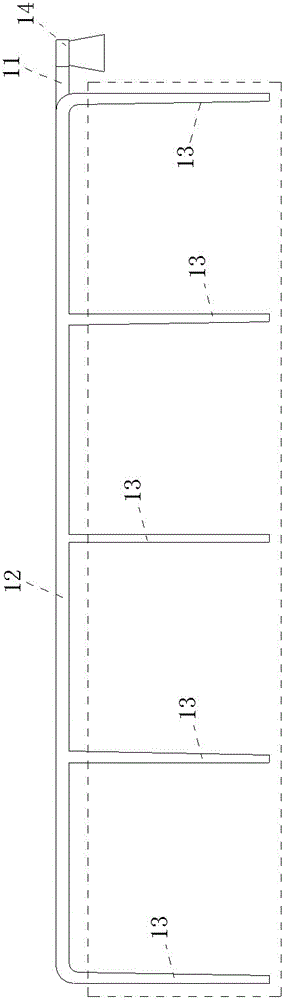
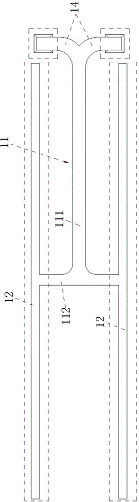
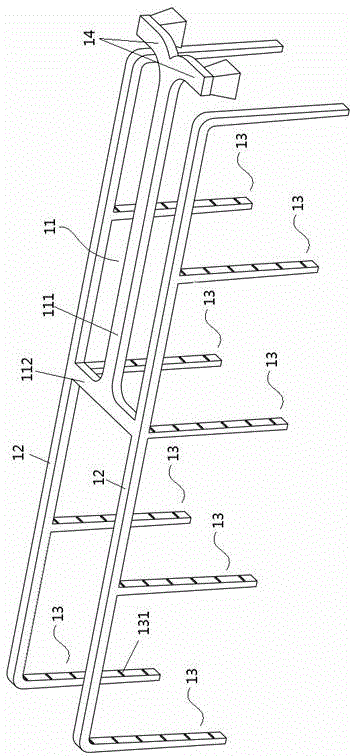
[0021] Embodiments of the air duct system of the energy storage cabin, such as Figure 1-3 As shown, the air duct system of the energy storage cabin includes a main air duct 11 , an intermediate air distribution duct 12 and branch air ducts 13 .

[0022] The main air duct 11 has an air inlet and an air outlet. In this embodiment, the main air duct 11 includes a longitudinal air duct 111 and a transverse air duct 112. The longitudinal air duct 111 extends along the front and rear directions, and the transverse air duct 112 extends along the left and right directions. The transverse air duct 112 and the longitudinal air duct 111 together form a T-shape, the air inlet is located at the end of the longitudinal air duct 111 away from the transverse air duct 112, the air outlet is located at both ends of the transverse air duct 112, and the air inlet of the main air duct 11 is at one end Connected with the air-introduction air channel 14, the air-induction air channel 14 is used to ...


PUM


Abstract

The invention relates to the field of electrical energy storage cabins, in particular to an energy storage cabin air duct system and an energy storage cabin with the air duct system. The energy storage cabin air duct system comprises a main air duct and two or more branch air ducts. The main air duct is provided with an air inlet and an air outlet communicated with the branch air ducts. The branch air ducts are divided into far-end branch air ducts and near-end branch air ducts from far to near according to the distance between the branch air ducts and the air inlet of the main air duct, the number of the far-end branch air ducts is at least one, and the cross sections of the far-end branch air ducts are gradually reduced from the end close to the main air duct to the other end. Due to the fact that the branch air ducts of the energy storage cabin air duct system are divided into the far-end branch air ducts and the near-end branch air ducts from far to near according to the distance between the branch air ducts and the air inlet of the main air duct and the cross sections of the far-end branch air ducts are gradually reduced from the end close to the main air duct to the other end, air pressure in the far-end branch air ducts can be maintained easily, it is promoted that the air outflow speeds of the branch air ducts are kept roughly the same, and finally the performance and the temperature control effect of a temperature control system of an energy storage device are guaranteed.

Description

technical field [0001] The invention relates to the field of electric energy storage cabins, in particular to an energy storage cabin air duct and an energy storage cabin using the air duct. Background technique [0002] With the rapid development of new energy technology, energy storage cabins, mainly energy storage devices such as batteries and supercapacitors, have been widely used in new energy vehicles and other fields. In the process of use, since the energy storage equipment needs to be fully functional under certain temperature conditions, in order to ensure the smooth operation of the equipment, the cabin body of the energy storage cabin is equipped with a corresponding air duct system. Wherein the notification number is just disclosed relevant technology in the Chinese patent of CN203305826U. [0003] In the existing energy storage cabin, the air duct generally adopts a straight-through pipe air duct, which can send the wind from the air outlet of the air conditio...

Claims


Application Information

Patent Timeline
IPC IPC(8): B60K11/06B60K1/04
Inventor 王伟严华窦辉郭炎杰张永峰丁丽平吕志娟魏伟赵培勇李松磊
Owner XJ ELECTRIC
Why Eureka
Try Eureka