Power roller transmission line

A technology of transmission line and drum, applied in the field of transmission line, can solve the problems of increasing labor intensity of workers, unable to realize automatic operation, etc., and achieve the effect of reducing labor intensity

Inactive Publication Date: 2015-09-30
蔡钱玉
View PDF0 Cites 2 Cited by
  • Summary
  • Abstract
  • Description
  • Claims
  • Application Information

AI Technical Summary

Problems solved by technology

The roller conveyor line is a very common one, and is very popular for its simple structure and low cost. However, the existing roller conveyor line is usually unpowered, and the products on the conveyor line need to be manually pulled to reach the next process. position, which increases the labor intensity of workers to a certain extent, and cannot realize complete automation

Method used


Image

  • Power roller transmission line
  • Power roller transmission line

Examples


Embodiment Construction

[0011] The present invention will be further described below in conjunction with the accompanying drawings.

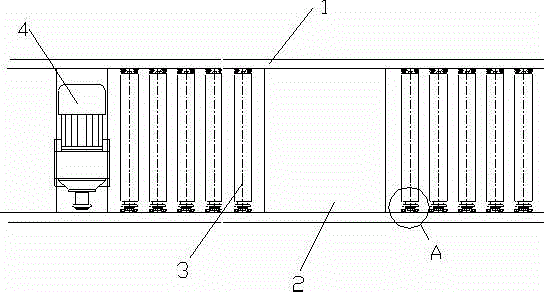
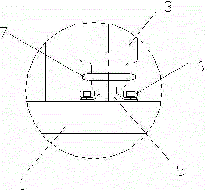
[0012] Such as figure 1 As shown, a power roller transmission line includes a transmission frame 1, a plurality of work table tops 2 are arranged on the transmission frame 1, and a plurality of rollers 3 are arranged at equal intervals between two adjacent work table tops 2 , the two ends of the drum 3 are fixed on the transmission frame 1 through the fixed plate 5 and the lock nut 6, and the drum 3 can rotate axially relative to the fixed plate 5, and the other parts of the drum 3 A pulley 7 is provided at one end, and a motor 4 is provided below the transmission frame 1, and the motor 4 drives the drum 3 through a belt. Driven by the motor 4, the drum 3 is powered and can rotate synchronously and uniformly, so that the product from the previous station is automatically transported to the next station, realizing automatic transportation without manual pulling and red...


PUM


Abstract

The invention discloses a power roller transmission line which comprises a transmission machine frame. A plurality of station tabletops are arranged on the transmission machine frame. A plurality of rollers are arranged between every two adjacent station tabletops at equal intervals. The two ends of each roller are fixed to the transmission machine frame through fixing plates and locking nuts. The rollers can axially rotate relative to the fixing plates. Belt wheels are arranged at one ends of the rollers. A motor is arranged below the transmission machine frame and drives the rollers through a belt. Under the drive of the motor, the rollers have power and can synchronously and uniformly rotate, products at the last station are automatically conveyed to the next station, automatic conveying is achieved, no manual pulling is needed, and labor intensity is lowered.

Description

technical field [0001] The invention relates to a power drum transmission line, which belongs to the technical field of transmission lines. Background technique [0002] The transmission line is an essential equipment for the streamlined operation of the modern production workshop. The roller conveyor line is a very common one, and is very popular for its simple structure and low cost. However, the existing roller conveyor line is usually unpowered, and the products on the conveyor line need to be manually pulled to reach the next process. This increases the labor intensity of workers to a certain extent, and it is impossible to realize complete automation. Contents of the invention [0003] The technical problem to be solved by the present invention is to provide a power roller transmission line, which can make the rollers rotate synchronously and uniformly under the drive of the motor, realize automatic transportation, and reduce labor intensity without manual pulling....

Claims


Application Information

Patent Timeline
Patent Type & Authority Applications(China)
IPC IPC(8): B65G13/04B65G13/07
CPCB65G13/04B65G13/07
Inventor 蔡钱玉
Owner 蔡钱玉
Why Eureka
Try Eureka