Scissors fork lifting type auxiliary supporting mechanism capable of being locked at random position

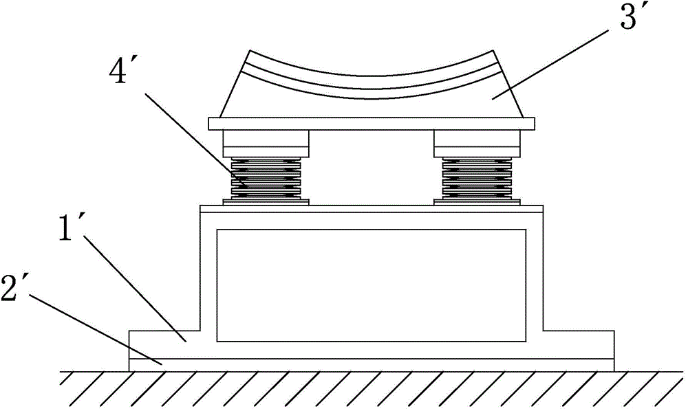
An auxiliary support and arbitrary position technology, which is applied in the direction of lifting frames and lifting devices, can solve the problems of limited specifications of the adjustment pad 2', small size of the adjustment pad 2', and excessive changes in the vertical size of the mechanism, so as to facilitate manual operation , the effect of reducing the requirement

Inactive Publication Date: 2015-09-30
BEIJING INST OF SPACE LAUNCH TECH +1
View PDF10 Cites 29 Cited by
  • Summary
  • Abstract
  • Description
  • Claims
  • Application Information

AI Technical Summary

Problems solved by technology

[0006] like figure 1 As shown, the existing auxiliary support mechanism is generally a fixed structure, including a mounting base 1', a bracket 3' is arranged above the mounting base 1', and two disc springs 4' are supported between the bracket 3' and the mounting base 1'. Between them, the launching product is placed on the bracket 3', and several adjusting pads 2' with different thicknesses are arranged under the mounting base 1', and the vertical position of the support mechanism can be adjusted by increasing or decreasing the number and thickness of the adjusting pads 2'. Purpose, this support mechanism can not meet the above requirements, the specific reasons are as follows:
[0007] (1) The size of the adjustment pad 2' is small, and it cannot realize the large displacement lifting function in the vertical direction, and cannot meet the use requirements;
[0008] (2) The specification of the adjustment pad 2' is limited, the adjustment function at any position cannot be realized, and the use requirements cannot be met;
[0009] (3) The use of oil cylinders or electric push rods to drive the auxiliary support mechanism of the above-mentioned fixed structure to lift will cause the vertical dimension of the mechanism to change too much, which cannot meet the installation space requirements

Method used


Image

  • Scissors fork lifting type auxiliary supporting mechanism capable of being locked at random position
  • Scissors fork lifting type auxiliary supporting mechanism capable of being locked at random position
  • Scissors fork lifting type auxiliary supporting mechanism capable of being locked at random position

Examples


Embodiment Construction

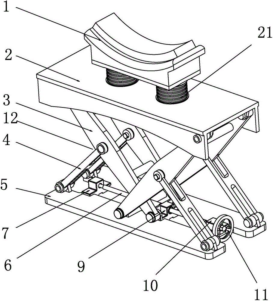
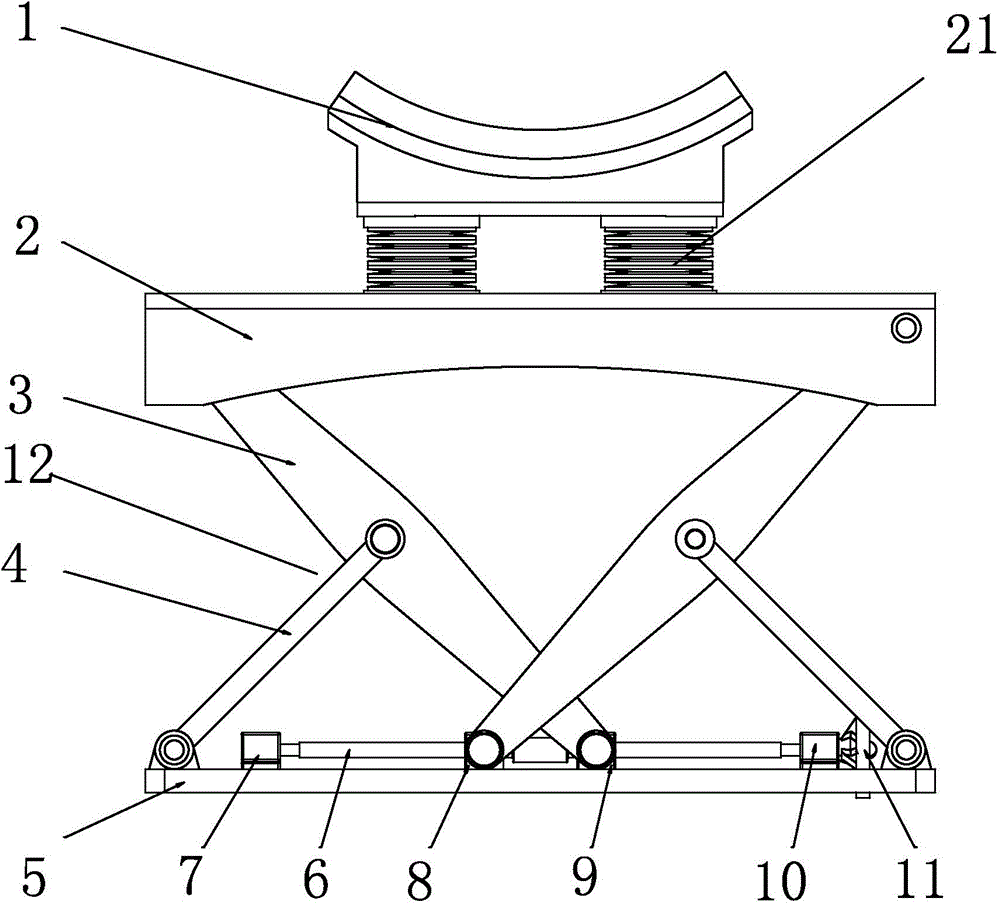
[0024] Such as figure 2 As shown, a scissor lifting auxiliary support mechanism that can be locked at any position in the present invention includes a bracket 1 and a top plate 2 below it. The bracket 1 and the top plate 2 are supported by two vertical Disc springs 21 arranged parallel to each other are fixedly connected. A bottom plate 5 is arranged below the top plate 2, and a screw rod 6 is arranged horizontally along the length direction of the bottom plate 5. For the convenience of fixing the screw rod 6 and ensuring the fixing effect of the screw rod 6, the screw rod 6 passes through the fixing seats 7, 7, The second fixed seat 10 is installed on the base plate 5 . Both ends of the screw rod 6 are fixed by two fixed seats, and its own movement is restricted. During the lifting movement of the supporting mechanism, the screw rod 6 will not move along its own axial or radial direction, effectively ensuring the adjustment accuracy of the lifting movement.

[0025] combin...


PUM


Abstract

The invention relates to a scissors fork lifting type auxiliary supporting mechanism capable of being locked at a random position. The scissors fork lifting type auxiliary supporting mechanism comprises a bracket and a top plate below the bracket. The bracket is fixedly connected with the top plate through two disc springs, a base plate is positioned below the top plate, a screw is horizontally arranged in the length direction of the base plate, a hand wheel is installed on the outer side of one end of the screw, and the middle of the screw is in threaded connection with a first sliding block and a second sliding block which are arranged at intervals. When the hand wheel is rotated, the first sliding block and the second sliding block can perform opposite-direction movements in the axial direction of the screw, four groups of linkage mechanisms are further arranged between the top plate and the base plate, the upper ends of the linkage mechanisms are hinged to the top plate, the lower ends of the linkage mechanisms are hinged to the first sliding block and the second sliding block respectively, and the first sliding block and the second sliding block can drive each group of linkage mechanisms to perform lifting movements when moving. The supporting mechanism can reliably support a product and have a large displacement lifting function, can perform fine adjustment of the vertical position, can be reliably locked at the random position, is small in vertical dimension and meets the installing space requirements.

Description

technical field [0001] The invention relates to a support mechanism, in particular to a liftable support mechanism used in the firing process of weapons. Background technique [0002] In the field of weapon thermal launch technology, during the storage and transportation of launch products, auxiliary mechanisms are required to support the product at an appropriate position and bear part of the load of the product to ensure that the load distribution of the product meets the requirements. For some models of products, the auxiliary support mechanism also needs to meet the following requirements: [0003] (1) In order to meet the requirements of raising the supporting product and retracting to make way for the space, the auxiliary supporting mechanism needs to have a large displacement lifting function along the vertical direction; [0004] (2) In order to adapt to vertical processing, meet installation error requirements, and ensure that the mechanism supports the product, th...

Claims


Application Information

Patent Timeline
Patent Type & Authority Applications(China)
IPC IPC(8): B66F7/06B66F7/28
CPCB66F7/0608B66F7/0658B66F7/28
Inventor 刘奇贾延奎张博宇吴新跃白文龙杭立杰邓海潮王岗罡
Owner BEIJING INST OF SPACE LAUNCH TECH
Why Eureka
Try Eureka