Large-range uniform light distributing method for LED high-pole lamp

A LED high pole light, a wide range of technology, applied in the field of LED lighting, can solve the problems of low light utilization efficiency, poor divergence, light spots and other problems, achieve good lighting effect, high lighting efficiency, and reduce light loss.

Inactive Publication Date: 2015-09-30
LUDONG UNIVERSITY +1
View PDF5 Cites 6 Cited by
  • Summary
  • Abstract
  • Description
  • Claims
  • Application Information

AI Technical Summary

Problems solved by technology

However, because the light emitted by the light-emitting chip of the LED light source is a straight line, its directivity is too high and the divergence is not good, so how to do a good light distribution has become the subject of people's research
As a lamp for large-scale lighting, high pole lights are particularly difficult to distribute light. Most of the LED high pole lights on the market now use a single-angle lens for light distribution. Not only is the light utilization efficiency low, but also there will be spots and dark areas. The use of lamps brings a lot of inconvenience, so it is more and more desired by people to study a low-cost, easy-to-implement method of LED high pole lamps with large-scale uniform light distribution.

Method used


Image

  • Large-range uniform light distributing method for LED high-pole lamp
  • Large-range uniform light distributing method for LED high-pole lamp
  • Large-range uniform light distributing method for LED high-pole lamp

Examples


Embodiment Construction

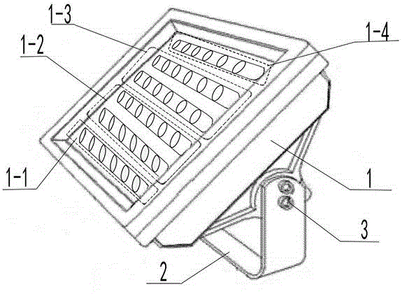
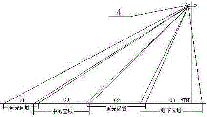
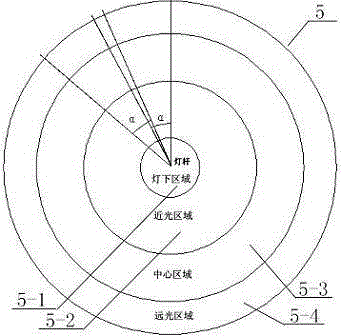
[0020] A method for large-scale uniform light distribution of LED high pole lights, such as Figure 1-3 As shown, it includes a lamp body 1, a mounting bracket 2, and an adjustment device 3 for adjusting the irradiation angle of the lamp body. The lamp body 1 uses a variety of lenses with different beam angles to achieve secondary light distribution, and all the lenses are in the The lateral direction of the irradiated area 5 adopts a symmetrical light distribution method, and the lateral beam angle cannot be smaller than the ratio of the irradiated angle to the number of single rows of lamps in the lateral direction of the entire high pole lamp; The longitudinal direction of the irradiated area 5 adopts an asymmetrical light distribution method, so that the outgoing light forms overlapping equal irradiated surfaces in the irradiated area 5. By adjusting the power ratio between the lenses on the lamp, the equal irradiated surfaces The intensity of light is kept consistent to a...


PUM


Abstract

The invention discloses a large-range uniform light distributing method for an LED high-pole lamp. The LED high-pole lamp comprises a lamp body and a mounting support, the mounting support is provided with an adjusting device used for adjusting irradiation angle of the lamp body, various lenses of different light beam angles can be mixedly used in the lamp body for secondarily distributing light, and the lenses symmetrically distribute light transversely in the irradiated area, and the transverse light beam angle is not smaller than the ratio of the irradiation angle to the number of the lamps, and light emitted from two transversely adjacent lamps on the same high-pole lamp can be stacked transversely in the irradiated area. Longitudinally, the lenses asymmetrically distribute light, and outgoing light can form a mutually stacked equal irradiation surface within the irradiated area, so that power ratio among the lenses of the lamps can be adjusted so as to enable light intensity of the equal irradiation surfaces to be consistent, and large-range uniform light distribution is realized.

Description

technical field [0001] The invention relates to the field of LED lighting, in particular to a method for uniform light distribution of large-scale lighting of LED high pole lamps. Background technique [0002] High-pole lamps have the advantages of high poles, large irradiation range, and long irradiation distance. They are widely used in city squares, overpasses, airports, railway stations, ports, and other places where people, vehicles, and goods flow frequently. Traditional high pole light sources are mostly high-intensity light sources such as high-pressure sodium lamps or metal halide lamps. However, due to the disadvantages of the above-mentioned light sources, such as high power consumption, low light efficiency, short service life, and unsatisfactory light distribution, the use cost of high pole lights has been constantly increasing. stay high. [0003] With the development of optoelectronic technology, LED light-emitting semiconductors have become a new generation ...

Claims


Application Information

Patent Timeline
Patent Type & Authority Applications(China)
IPC IPC(8): F21S8/00F21V21/14F21W131/10F21Y101/02
CPCF21S8/085F21V21/14F21W2131/10
Inventor 王福才周鲁苹陈晓东曹光生
Owner LUDONG UNIVERSITY
Why Eureka
Try Eureka