System and method for carrying out radiation survey on moving target
What is Al technical title?
Al technical title is built by PatSnap Al team. It summarizes the technical point description of the patent document.
A moving target and radiation source technology, applied in the field of radiation inspection of moving targets, can solve problems such as low inspection efficiency, increased equipment and labor input costs, and inability to carry out inspections on moving targets, so as to achieve high security inspection efficiency and ensure personnel safety. Effect
Active Publication Date: 2015-09-30
พาวเวอร์สแกน ไฮเทค โค แอลทีดี
View PDF4 Cites 16 Cited by
Summary
Abstract
Description
Claims
Application Information
AI Technical Summary
This helps you quickly interpret patents by identifying the three key elements:
Problems solved by technology
Method used
Benefits of technology
Problems solved by technology
[0004] After a lot of research and analysis, it is found that although the above-mentioned systems can complete the basic inspection tasks of moving targets, there are still certain disadvantages, that is, due to the limitation of their system structure, this type of system can only perform inspections on moving targets from a single specific direction. Inspection, but it is impossible to inspect moving targets traveling in other directions. For applications where the ground traffic network is complex and the system occupies a limited area, this type of system will not be available, resulting in low inspection efficiency and increased equipment and labor input costs.
Method used
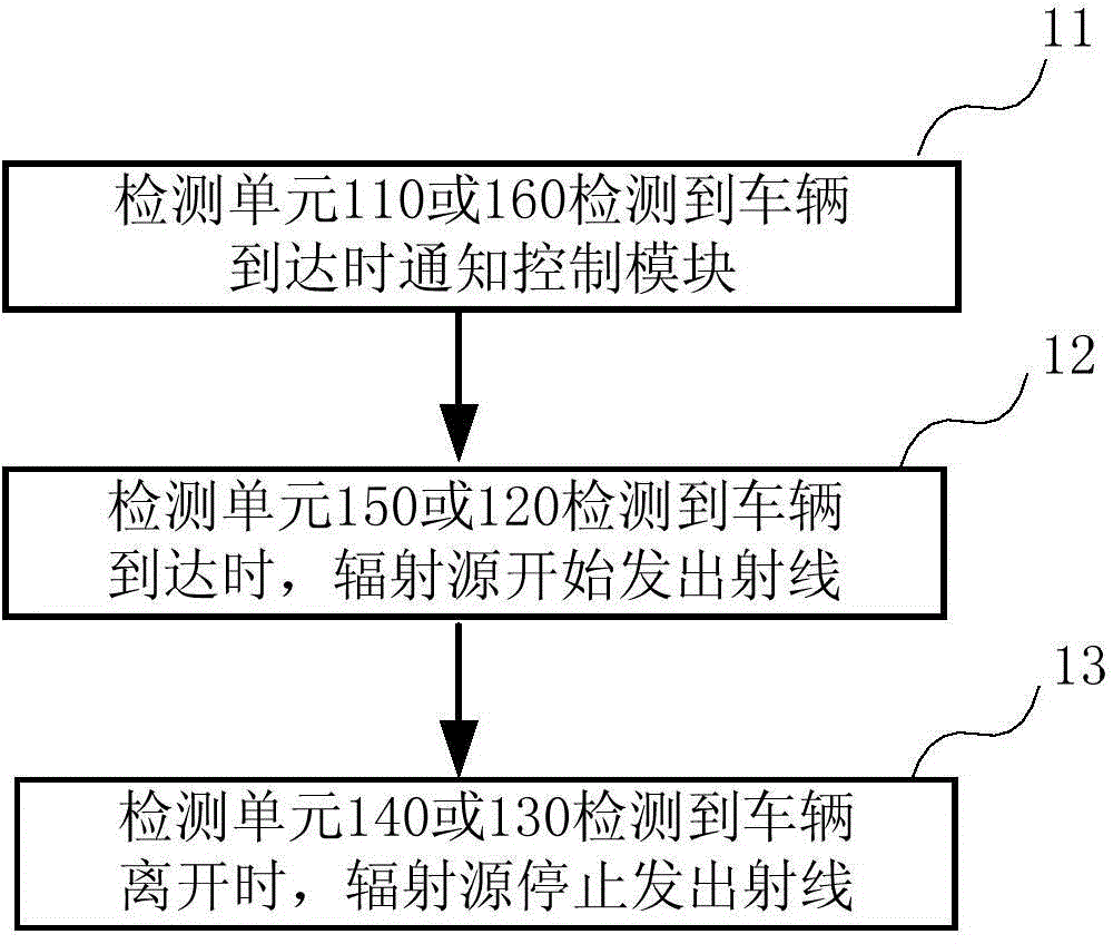
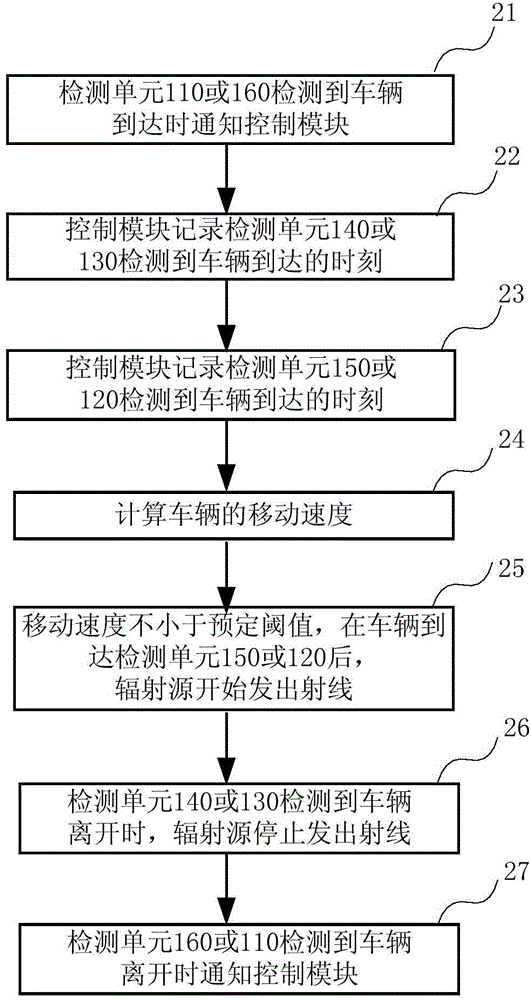
Image
Click on the blue label to locate the original text in one second.
Reading with bidirectional positioning of images and text.
Examples
Embodiment Construction
[0033] The technical solutions of the present invention will be described in detail below in conjunction with the accompanying drawings and specific embodiments.
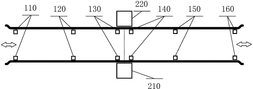
[0034] figure 1 It shows a schematic structural diagram of a radiation inspection system according to an embodiment of the present invention, wherein the radiation source 210 and the array radiation detector 220 are respectively located on both sides of the detection channel. When a moving object such as a vehicle passes by, the radiation source 210 emits scanning rays to detect The device 220 receives the radiation that penetrates the moving target, converts it into corresponding digital quantities, and forms a digital radiation image after being processed by the imaging system (not shown in the figure), completing the radiation scanning security inspection process. During the scanning process, the radiation source rays are collimated by the collimator and are limited in the scanning area, and the objects beyond th...
PUM
Abstract
A system and method for radiation inspection on a moving object. The system comprises a radiation source and a radiation detector. Rays emitted by the radiation source are limited in a scanning area. The scanning area is provided by a first boundary surface and a second boundary surface. The system also comprises: multiple detection units (110, 120, 130, 140, 150, 160) arranged along a detection channel in turn and used for triggering and sending a signal when detecting that the moving object arrives or leaves; and a control module used for receiving signals sent by the multiple detection units (110, 120, 130, 140, 150, 160) and controlling the radiation source according to the received signal. The first to third detection units (110, 120, 130) among the multiple detection units (110, 120, 130, 140, 150, 160) are located at one side of the scanning area and near the first boundary surface. The fourth to sixth detection units (140, 150, 160) among the multiple detection units (110, 120, 130, 140, 150, 160) are located at the other side of the scanning area and near the second boundary surface. The system and the method can implement radiation inspection on moving objects travelling in multiple directions.
Description
technical field [0001] The invention relates to the technical field of radiation scanning, in particular to a system and method for radiation inspection of a moving target. Background technique [0002] At present, the use of high-energy radiation to automatically scan and inspect high-speed moving targets such as moving vehicles can complete the security inspection of smuggled, illegal, and prohibited items without interrupting the high-speed passage of vehicles, which is ideal for 100% inspection of vehicles means. [0003] Existing inspection systems of this type usually have at least one radiation source and a matching collimator. The collimator collimates the rays emitted by the radiation source into a fan-shaped beam, and several sensors are used to detect the target moving in a certain direction. A detector array is arranged on the opposite side of the radiation source, which receives the radiation that penetrates the moving target and forms a digital image, through ...
Claims
Application Information
Patent Timeline
Application Date:The date an application was filed.
Publication Date:The date a patent or application was officially published.
First Publication Date:The earliest publication date of a patent with the same application number.
Issue Date:Publication date of the patent grant document.
PCT Entry Date:The Entry date of PCT National Phase.
Estimated Expiry Date:The statutory expiry date of a patent right according to the Patent Law, and it is the longest term of protection that the patent right can achieve without the termination of the patent right due to other reasons(Term extension factor has been taken into account ).
Invalid Date:Actual expiry date is based on effective date or publication date of legal transaction data of invalid patent.