Varistor

A varistor, rectangular technology, applied in the direction of resistors, overvoltage protection resistors, varistors, etc., can solve problems such as thermal runaway effect, overheating of varistors, permanent change of V-I characteristics, etc., and achieve the effect of short discharge time

Inactive Publication Date: 2015-09-30
M&IMATERIALS LTD
View PDF4 Cites 1 Cited by
  • Summary
  • Abstract
  • Description
  • Claims
  • Application Information

AI Technical Summary

Problems solved by technology

Severe overheating of the varistor, say well over 200°C, can lead to permanent changes in the V-I characteristics of the disc
Thermal runaway eff

Method used


Image

  • Varistor
  • Varistor
  • Varistor

Examples


Embodiment Construction

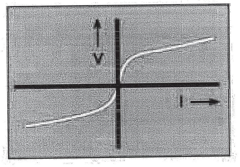
[0063] exist figure 1 It can be seen that the voltage-current relationship of the varistor of the present invention is symmetrical. Traditionally, the relationship is expressed by equations (3) and (4):

[0064] V=CI β (3)

[0065] I=HV α (4)

[0066] in,

[0067] V is the terminal voltage of the non-linear resistor

[0068] I is the current flowing through the non-linear resistor

[0069] C is the voltage across the nonlinear resistor at a current of 1A

[0070] H is the current flowing through the nonlinear resistor at 1V

[0071] β and α are nonlinear factors (β=1 / α)

[0072] The "C" value of a varistor depends largely on the geometry of the varistor, the manufacturing method used to produce it, and the number of disks connected in series or parallel, while the "β" value largely depends on the Materials and working electrical stress. The varistors of the present invention are typically produced over a continuous range of C values ​​and beta values ​​in the ...


PUM

PropertyMeasurementUnit
Lengthaaaaaaaaaa

Abstract

The present invention relates to a unit comprising a plurality of varistors, specifically for the purposes of overvoltage protection in synchronous generator exciter discharge systems. Compared with existing varistor units, the unit of the invention is able to be transported more efficiently, is more compact, and requires fewer individual varistor units to be placed in a synchronous generator exciter discharge system while still achieving the required thermal and electrical ratings to perform to the desired requirements.

Description

technical field [0001] The invention relates to a varistor device, especially for overvoltage protection in a synchronous generator exciter discharge system. Background technique [0002] Exciters in synchronous generators are used to provide DC feed to the field windings mounted on the generator rotor. In order to prevent the excitation system from being damaged during the closing process, there must be a suitable device to discharge the energy stored in the field coil. For many years, silicon carbide varistors, such as those manufactured and sold by M&I Materials under the trade name The silicon carbide varistors of the company provide a reliable solution for exciter discharge applications, and silicon carbide varistors are used by many first-class OEMs in famous power projects in the world, such as the Three Gorges Dam on the Yangtze River in China. [0003] The excitation system used on a synchronous generator can be in one of two forms. The first is called a brushle...

Claims


Application Information

Patent Timeline
IPC IPC(8): H01C7/10H01C7/12H02H9/02H01C17/00
CPCH02H3/20H02H3/44H01C13/02H01C7/12H02H9/04
Inventor 杰夫·罗伯逊
Owner M&IMATERIALS LTD
Why Eureka
Try Eureka