
Improved MMC (modular multi-level converter) structure with direct current fault clearing capacity

A modular multi-level, DC fault technology, used in emergency protection circuit devices for limiting overcurrent/overvoltage, output power conversion devices, AC power input conversion to DC power output and other directions, can solve the problem of double thyristor Insufficient protection range, slow fault isolation speed, limited fault types, etc., to achieve the effect of increasing the protection range, accelerating the decay speed of fault current, and reducing overcurrent hazards

Active Publication Date: 2015-09-30
TIANJIN UNIV
View PDF3 Cites 14 Cited by
  • Summary
  • Abstract
  • Description
  • Claims
  • Application Information

AI Technical Summary

Problems solved by technology

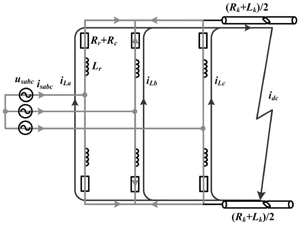
However, because the double thyristor method converts the fault on the DC side into a three-phase short-circuit fault on the AC side, it will cause long-term overcurrent on the AC side; at the same time, the fault current is naturally attenuated according to the resistance component in the DC fault circuit, so its fault isolation speed Slows down as the fault gets closer, especially for metallic faults near the converter outlet, taking a long time to isolate the fault
In summary, the above-mentioned double thyristor method has the disadvantages of insufficient protection range and limited protection fault types, so corresponding improvement measures must be taken to solve the above-mentioned deficiencies in practical engineering applications

Method used


Image

  • Improved MMC (modular multi-level converter) structure with direct current fault clearing capacity
  • Improved MMC (modular multi-level converter) structure with direct current fault clearing capacity
  • Improved MMC (modular multi-level converter) structure with direct current fault clearing capacity

Examples


Embodiment Construction

[0015] The technical solution of the present invention will be described in further detail below in conjunction with the accompanying drawings and specific embodiments.

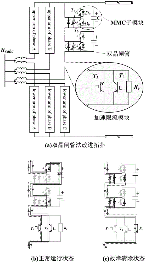
[0016] Some improvements are made to the topology of the Modular Multilevel Converter (MMC) based on the dual thyristor method, such as figure 1 As shown in (a): the double thyristor method adds anti-parallel double thyristors in each MMC sub-module of the MMC converter. On this basis, the present invention connects an accelerated current limiting module in series in each bridge arm of the MMC , the module consists of two anti-parallel IGBTs and a parallel resistor R c constitute. In the picture: T 1 , T 2 For anti-parallel IGBTs, R c It is the resistor connected in series on the bridge arm of the converter after the fault occurs.

[0017] When the DC system is running normally, the IGBTs of the acceleration current limiting modules connected in series in each bridge arm are in the on state. At this tim...


PUM


Abstract

The invention discloses an improved MMC (modular multi-level converter) structure with direct current fault clearing capacity. The improved MMC structure is characterized in that on the basis of a double-thyristor method, an accelerating current-limiting module is connected in series into each arm of an MMC; during normal operation of a system, all thyristors are in a disconnected state, an IGBT (insulated gate bipolar transistor) in each accelerating current-limiting module is in a connected state, and a current-limiting resistor Rc is in a bypass state all along; when a fault occurs on the direct current side of the system, all the IGBTs Ta and Tb in each MMC sub-module are disconnected and all the thyristors are connected, fault current is prevented from being fed into the direct current fault point by a direct current side power supply, meanwhile, all the IGBTs in the accelerating current-limiting modules of six arms are disconnected simultaneously, the accelerating current-limiting resistor Rc is added, and the fault isolation speed is increased and overcurrent on the direct current side is prevented. The improved MMC structure is applicable to all the direct current fault types, and the protection range is enlarged; meanwhile, the fault current attenuation speed is increased, and time for fault isolation is shortened greatly; overcurrent on the direct current side is reduced, and overcurrent harm on the direct current side is reduced greatly.

Description

technical field [0001] The invention relates to the field of power system protection and control, in particular to a DC fault processing method. Background technique [0002] Fast DC fault isolation is a key technology in the development of flexible DC systems. When a DC fault occurs in the flexible DC system, the fault current of the whole system rises sharply, seriously endangering the safe and reliable operation of the system. However, none of the existing converters can realize the self-clearing of the DC fault, and relevant measures must be taken to remove the faulty line. However, since the fault current does not have a natural zero-crossing point during a DC fault, it is difficult to extinguish the arc of the DC circuit breaker. Therefore, the technology of large-capacity DC circuit breakers is far from reaching the level of commercial application. Therefore, a large number of scholars at home and abroad have focused on the converter structure and corresponding cont...

Claims


Application Information

Patent Timeline
IPC IPC(8): H02H9/02H02M7/483
Inventor 李斌李晔
Owner TIANJIN UNIV
Learn More