Method and system for message transmission

A technology for forwarding messages and messages, applied in the field of cloud computing, can solve unsolvable problems and achieve obvious advantages

Active Publication Date: 2015-09-30
HUAWEI TECH CO LTD
View PDF2 Cites 11 Cited by
  • Summary
  • Abstract
  • Description
  • Claims
  • Application Information

AI Technical Summary

Problems solved by technology

[0010] The embodiment of the present invention provides a method and system for forwarding messages, aiming to solve two problems that cannot be solved when the existing VXLAN technology implements network virtualization

Method used


Image

  • Method and system for message transmission
  • Method and system for message transmission
  • Method and system for message transmission

Examples


Embodiment 1

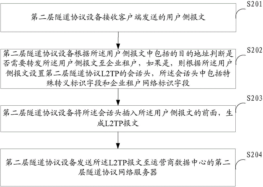
[0057] figure 2 The implementation process of the method for forwarding a message provided by Embodiment 1 of the present invention is shown, and the receiving client of the layer-2 tunneling protocol device is taken as an example for illustration, and the details are as follows:

[0058] In step S201, the layer-2 tunneling protocol device receives the user-side packet sent by the client.

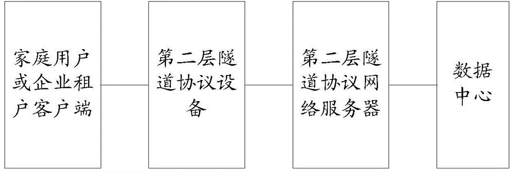
[0059] In this embodiment, the client sends the user-side message to the layer-2 tunneling protocol device, and the layer-2 tunneling protocol device processes the user-side message and sends it to the LNS. The user of the client may be an enterprise tenant or an ordinary household broadband user.

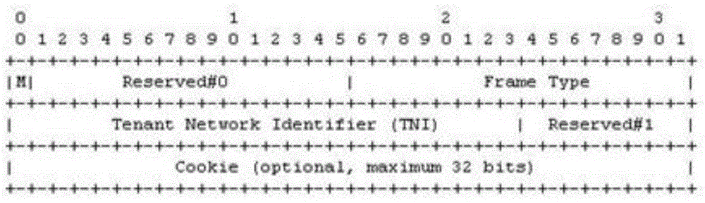
[0060] In step S202, the layer-2 tunneling protocol device judges whether it needs to forward the user-side message to the enterprise tenant according to the destination address included in the user-side message, and if so, sets the first A session header of the Layer 2 Tunneling Protocol L2T...

Embodiment 2

[0087] Figure 4 A specific structural block diagram of the layer-2 tunneling protocol device provided by Embodiment 2 of the present invention is shown. For convenience of description, only parts related to the embodiment of the present invention are shown. The layer-2 tunneling protocol device can be connected between the client and the layer-2 tunneling protocol network server, together with the client and the layer-2 tunneling protocol network server to form a message forwarding system, the layer-2 tunneling protocol device 4 includes: a user side message receiving unit 41, a message type judging unit 42, a session header setting unit 43, an L2TP message generating unit 44 and an L2TP message sending unit 45.

[0088] Wherein, the user-side message receiving unit 41 is configured to receive the user-side message sent by the client;

[0089] A message type judging unit 42, configured to judge whether the user-side message needs to be forwarded to an enterprise tenant accor...

Embodiment 3

[0103] Figure 5 A specific structural block diagram of the layer-2 tunneling protocol device provided by Embodiment 3 of the present invention is shown. For convenience of description, only parts related to the embodiment of the present invention are shown. The layer-2 tunneling protocol device can be connected between the client and the layer-2 tunneling protocol network server, together with the client and the layer-2 tunneling protocol network server to form a message forwarding system, the layer-2 tunneling protocol device 5 includes: a receiver 51, a processor 52 and a transmitter 53.

[0104] Wherein, the transmitter 51 is used to receive the user-side message sent by the client;

[0105] Processor 52, configured to judge whether the user-side message needs to be forwarded to the enterprise tenant according to the destination address included in the user-side message, and if the user-side message needs to be forwarded to the enterprise tenant, according to the user-sid...


PUM


Abstract

The present invention is applied to the field of cloud computing, and provided are a packet forwarding method and system. The method comprises: receiving, by a layer 2 tunneling protocol device, a user-side packet sent by a client; according to a destination address contained in the user-side packet, judging, by the layer 2 tunneling protocol device, whether the user-side packet is required to be forwarded to an enterprise tenant, and if so, setting a session header of a layer 2 tunneling protocol (L2TP) according to the user-side packet, the session header comprising a special escaped identifier field and an enterprise tenant network identifier field; inserting, by the layer 2 tunneling protocol device, the session header in the front of the user-side packet so as to generate an L2TP packet; and sending, by the layer 2 tunneling protocol device, the L2TP packet to a layer 2 tunneling protocol network server of an operator data centre. The present invention will not bring an additional data header, and will not cause an MTU problem of a network device, so that the advantage caused by an escape action is obvious.

Description

technical field [0001] The invention belongs to the field of cloud computing, and in particular relates to a method and a system for forwarding messages. Background technique [0002] The rapid development of cloud computing (Cloud Computing) technology has completely changed people's understanding of computing resources, gradually shifting from the traditional perspective of focusing on physical hosts, physical networks, and physical resources to focusing on virtual hosts, virtual networks, and virtual resources. A group of leading enterprises took the lead in establishing their own private cloud and opening it to the outside world during this transformation process, and achieved great success, further promoting the development of cloud computing technology and market. [0003] In view of the existing business cases and the advantages of private clouds that can make full use of existing computing resources and reduce IT operation and maintenance costs and energy consumption...

Claims


Application Information

Patent Timeline
Patent Type & Authority Applications(China)
IPC IPC(8): H04L29/06H04L12/46
CPCH04L12/4633H04L45/74H04L69/324
Inventor 管红光
Owner HUAWEI TECH CO LTD
Why Eureka
Try Eureka