Four-wheel drive wire feeding mechanism

A four-wheel drive, transmission mechanism technology, applied in the transportation of filamentous materials, thin material processing, transportation and packaging, etc., can solve the problems of affecting the terminal crimping process, low work efficiency, weak transmission power, etc., to improve the overall The effect of work efficiency, good wire feeding stability and high work efficiency

Active Publication Date: 2015-10-07
ZHONGSHAN YATAI MACHINERY
View PDF8 Cites 12 Cited by
  • Summary
  • Abstract
  • Description
  • Claims
  • Application Information

AI Technical Summary

Problems solved by technology

[0002] With the development of the electronics industry, in order to improve production efficiency, the division of labor in manufacturing is becoming more and more detailed. At present, there is an industry specializing in terminal crimping, while traditional terminal crimping needs to be done manually from wire feeding to terminal crimping. The efficiency is low, and the error is large, so now there are some special equipment for crimping terminals, which can automatically complete terminal crimping. The wire feeding mechanism is an important part of the terminal machine. The stability and speed of wire feeding are related to the terminal. The overall working efficiency of the machine, but the current wire feeding mechanism mostly adopts a two-wheel drive or a wire feeding mechanism with one side active and one side driven. The transmission power is weak, the wire feeding stability is poor, and the wire feeding speed is slow and the work efficiency is low. Greatly affects the subsequent terminal crimping process

Method used


Image

  • Four-wheel drive wire feeding mechanism
  • Four-wheel drive wire feeding mechanism
  • Four-wheel drive wire feeding mechanism

Examples


Embodiment Construction

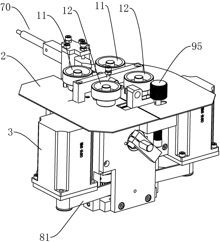
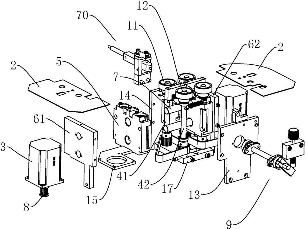
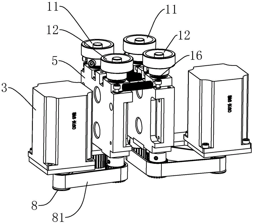
[0024] refer to Figure 1 to Figure 7 , Figure 1 to Figure 7 It is a structural schematic diagram of a specific embodiment of the present invention. As shown in the figure, a four-wheel drive wire feeding mechanism includes a frame, a cover plate 2 arranged on the frame, and two sets of wire feeding wheel mechanisms respectively arranged on both sides of the frame , the frame consists of a base plate 17, a front panel 14, a rear panel 13, a left vertical plate 61, a right vertical plate 62, and the wire feeding wheel mechanism includes a motor 3, a first transmission shaft 41, a second transmission shaft 42, a first Wire feeding wheel 11, the second wire feeding wheel 12, the motor 3 is arranged downwards and is connected to the lower ends of the first transmission shaft 41 and the second transmission shaft 42 through a transmission mechanism such as a belt transmission mechanism, a gear transmission mechanism, etc. It can drive the first transmission shaft 41 and the second...


PUM


Abstract

The invention discloses a four-wheel drive wire feeding mechanism. The mechanism comprises a frame, a cover plate arranged on the frame, and two sets of wire feeding wheel mechanisms respectively arranged at the two sides of the frame, wherein the wire feeding wheel mechanisms comprise motors, first and second transmission shafts and first and second wire feeding wheels; the motors are respectively connected to the lower ends of the first and second transmission shafts through transmission mechanisms, and can drive the first and second transmission shafts to synchronously rotate; the upper ends of the first and second transmission shafts extend outside the cover plate; the first and second wire feeding wheels are respectively arranged at the upper ends of the first and second transmission shafts; the first and second wire feeding wheels of the two sets of wire feeding wheel mechanisms are pairwise corresponding, and reversely rotate; in working, leads are respectively inserted between the first wire feeding wheels and the second wire feeding wheels of the two sets of wire feeding wheel mechanisms to realize a wire feeding function; and four wheels all have power, so that the conveying power is strong, the wire feeding stability is good, the wire feeding speed is fast, the working efficiency is high, and the improvement of whole working efficiency of terminal equipment is facilitated.

Description

technical field [0001] The invention relates to a four-wheel drive wire feeding mechanism. Background technique [0002] With the development of the electronics industry, in order to improve production efficiency, the division of labor in manufacturing is becoming more and more detailed. At present, there is an industry specializing in terminal crimping, while traditional terminal crimping needs to be done manually from wire feeding to terminal crimping. The efficiency is low, and the error is large, so now there are some special equipment for crimping terminals, which can automatically complete terminal crimping. The wire feeding mechanism is an important part of the terminal machine. The stability and speed of wire feeding are related to the terminal. The overall working efficiency of the machine, but the current wire feeding mechanism mostly adopts a two-wheel drive or a wire feeding mechanism with one side active and one side driven. The transmission power is weak, the w...

Claims


Application Information

Patent Timeline
IPC IPC(8): B65H51/08B65H57/12
Inventor 赵维甘松奇李业
Owner ZHONGSHAN YATAI MACHINERY
Why Eureka
Try Eureka