
A method for laying cables in a hull bridge

A technology of cable laying and cab, which is applied in the field of cable laying in the hull cab, can solve the problems of cab equipment control or signal failure, increased structure, difficult construction, and unfavorable maintenance, etc., to achieve good fire performance, low cost, and easy construction The effect of easy maintenance

Active Publication Date: 2017-07-25
JIANGSU HONGQIANG MARINE HEAVY IND
View PDF6 Cites 0 Cited by
  • Summary
  • Abstract
  • Description
  • Claims
  • Application Information

AI Technical Summary

Problems solved by technology

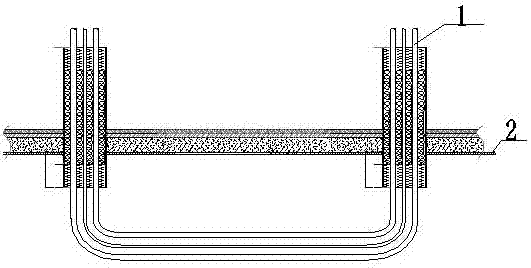
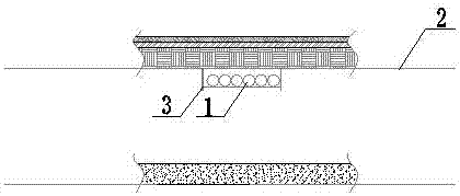
[0003] When laying cables in the ship's cab, there are two structures, the first one is as figure 1 As shown, the cable 1 passes through the deck 2 of the cab and is hidden on the back of the deck 2 of the cab. The disadvantage of this laying structure is that the cable 1 is exposed in the lower layer of the cab. If the lower layer catches fire, the cable will be burned, resulting in the control of the cab equipment. or signal failure; the second such as figure 2 As shown, in order to avoid cable exposure, the cable bracket 3 is added on the back of the cab deck 2 to protect the cable 1. The disadvantages are: since there are many horizontal and vertical profiles on the back of the cab deck 2, and the air duct and cable bracket staggered vertically and horizontally, increasing the structure is difficult to construct, and it is also not conducive to maintenance

Method used


Image

  • A method for laying cables in a hull bridge
  • A method for laying cables in a hull bridge
  • A method for laying cables in a hull bridge

Examples


Embodiment Construction

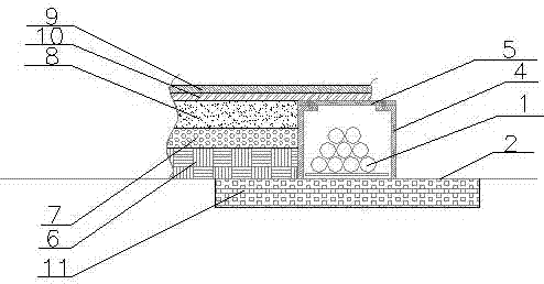
[0019] Such as figure 1 As shown, the present invention discloses a method for laying a cable 1 in a hull cab. The method is that the cable 1 is installed on the front of the cab deck 2 through the cable trough 4, and a fireproof layer is laid on the back of the cab deck 2 in the area where the cable trough 4 is located. .

[0020] The specific steps of the above method are as follows:

[0021] The first step is to lay cables: first install the cable groove 4 on the cab deck 2, then install the cable 1 in the cable groove 4, and when the cable 1 is installed, install the cable groove cover 5 at the notch of the cable groove 4;

[0022] The second step is to lay high-level layers: on the cab deck 2 around the cable trough 4, a sound-insulating rock wool layer 6, a lightweight deck covering layer 7 and a deck covering layer 8 are successively laid, and the lightweight deck covering layer adopts expanded perlite. The upper end surface of the deck coating layer 8 is flush with t...


PUM


Abstract

The invention relates to a hull navigation bridge cable laying method. According to the method, cables are installed on the front surface of a deck of a navigation bridge through a cable trough, and a fireproof layer is laid on the back surface of the deck of the navigation bridge in the area where the cables are disposed. The method specifically comprises the four steps of laying the cable trough, laying an equal-height layer, laying a floor and laying the fireproof layer, wherein the equal-height layer employs a sound insulation rock wool layer, a lightweight deck dressing layer and a deck dressing layer, and the fireproof layer employs ceramic cotton. The method has the following steps: through installing the cables on the front surface of the deck of the navigation bridge through the cable trough, the hull navigation bridge cable laying method can prevent the cables from damage, is convenient in construction and maintenance and enhances the fireproof performance due to additional arrangement of the fireproof layer on the back surface of the deck of the navigation bridge.

Description

technical field [0001] The invention relates to the field of ship manufacturing, in particular to a cable laying method for a ship cab. Background technique [0002] Ship electrical cable laying is a key link in ship electrical installation. The quality of the cable laying process directly affects whether the ship's power distribution system can work normally and safely, and whether the electrical equipment can operate effectively and reliably. [0003] When laying cables in the ship's cab, there are two structures, the first one is as figure 1 As shown, the cable 1 passes through the deck 2 of the cab and is hidden on the back of the deck 2 of the cab. The disadvantage of this laying structure is that the cable 1 is exposed in the lower layer of the cab. If the lower layer catches fire, the cable will be burned, resulting in the control of the cab equipment. or signal failure; the second such as figure 2 As shown, in order to avoid cable exposure, the cable bracket 3 is ...

Claims


Application Information

Patent Timeline
Patent Type & Authority Patents(China)
IPC IPC(8): H02G1/06H02G3/00
Inventor 徐国强任瑞华张志臣
Owner JIANGSU HONGQIANG MARINE HEAVY IND
Learn More