Transient energy protection method of transmission line with unified power flow controller
A technology of power flow controller and transmission line, applied in the direction of emergency protection circuit devices, electrical components, etc., can solve the problems of misjudgment of traditional relay protection, achieve the effect of avoiding inconstant changes in positive and negative polarity and improving reliability
- Summary
- Abstract
- Description
- Claims
- Application Information
AI Technical Summary
Problems solved by technology
Method used
Image
Examples
Embodiment 1
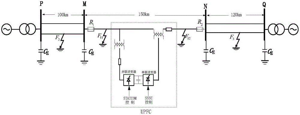
[0025] Embodiment 1: contain UPFC vertical line system simulation model such as figure 1 As shown, UPFC is installed at the midpoint of the line (75km away from MN), and the total length of line MN is 150km. The fault initial angle is 90°, the sampling rate is 20kHz, and the time window length is 3ms. Let the AG fault F occur at a distance of 60km from the M side between the M side and the UPFC input point on the line MN 11
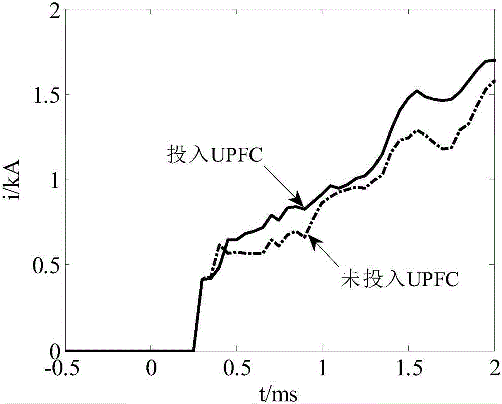
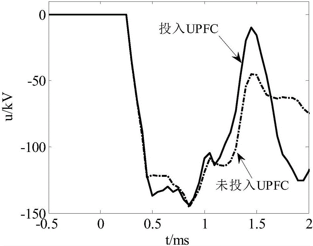
[0026] 1. Use the measurement terminal of the transmission line to obtain the influence of UPFC input on the fault current and voltage, such as figure 2 , image 3 shown. Calculate the instantaneous power according to formula (1) in the specification.
[0027] 2. According to the formula (2) in the manual, the instantaneous power is integrated to obtain the corresponding transient energy, such as Figure 4 shown.
[0028] 3. According to the formula (3) and (4) in the description, the sign of the transient energy is judged, by Figure 4 middle si...
Embodiment 2
[0030] Embodiment 2: contain UPFC vertical line system simulation model such as figure 1 As shown, UPFC is installed at the midpoint of the line (75km away from MN), and the total length of line MN is 150km. The fault initial angle is 90°, the sampling rate is 20kHz, and the time window length is 3ms. Let the AG fault F occur on the line PM 40km away from the M side 2 .
[0031] 1. Use the measuring end of the transmission line to obtain the influence of UPFC input on the fault current and voltage, and calculate the instantaneous power according to the formula (1) in the manual.
[0032] 2. According to the formula (2) in the manual, the instantaneous power is integrated to obtain the corresponding transient energy, such as Figure 5 shown.
[0033] 3. According to the formula (3) and (4) in the description, the sign of the transient energy is judged, by Figure 4 middle sign(E M )>0 and sign(E N ) 2 ) for M terminal relay R 1 For the reverse direction fault, for the N...
PUM
 Abstract
Description
Claims
Application Information
 - R&D
- Intellectual Property
- Life Sciences
- Materials
- Tech Scout
- Unparalleled Data Quality
- Higher Quality Content
- 60% Fewer Hallucinations
Browse by: Latest US Patents, China's latest patents, Technical Efficacy Thesaurus, Application Domain, Technology Topic, Popular Technical Reports.
© 2025 PatSnap. All rights reserved.Legal|Privacy policy|Modern Slavery Act Transparency Statement|Sitemap|About US| Contact US: help@patsnap.com


