Automatic riveting apparatus of loudspeaker U iron and basin stand

An automatic riveting and speaker technology, applied in the direction of sensors, electrical components, etc., can solve the problems of speaker products unqualified, operator injury, difficult operation, etc., to avoid the risk of injury, reduce labor difficulty and strength, and the structure is ingenious and reasonable Effect

Active Publication Date: 2015-10-07
WUXI JIEFU ELECTROACOUSTIC
View PDF4 Cites 11 Cited by
  • Summary
  • Abstract
  • Description
  • Claims
  • Application Information

AI Technical Summary

Problems solved by technology

This kind of process is difficult to operate, and it is easy to cause injury to the operator, and it is also easy to cause the speaker product to be unqualified due to the incorrect placement angle of the pot frame and U iron.

Method used


Image

  • Automatic riveting apparatus of loudspeaker U iron and basin stand
  • Automatic riveting apparatus of loudspeaker U iron and basin stand
  • Automatic riveting apparatus of loudspeaker U iron and basin stand

Examples


Embodiment Construction

[0016] The present invention will be further described below in conjunction with specific drawings and embodiments.

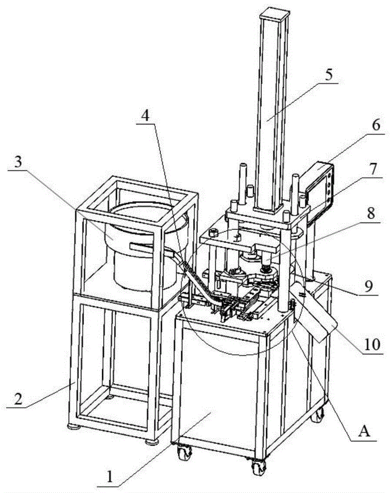
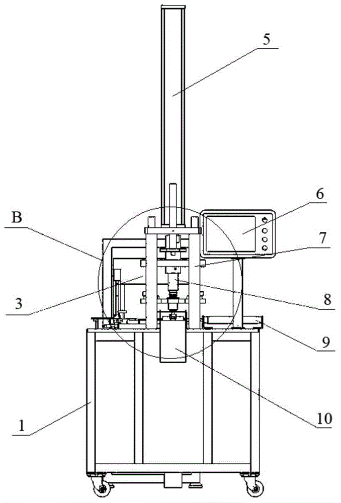
[0017] Such as Figure 1~Figure 4 As shown: the automatic riveting device of the speaker U iron and the basin frame in the embodiment is mainly composed of the machine platform 1, the U iron feeding and sorting mechanism, the U iron basin frame translation mechanism, the stamping mechanism, the finished product blanking chute 10, and the finished product pushing mechanism And form a complete set of electrical control box 6.

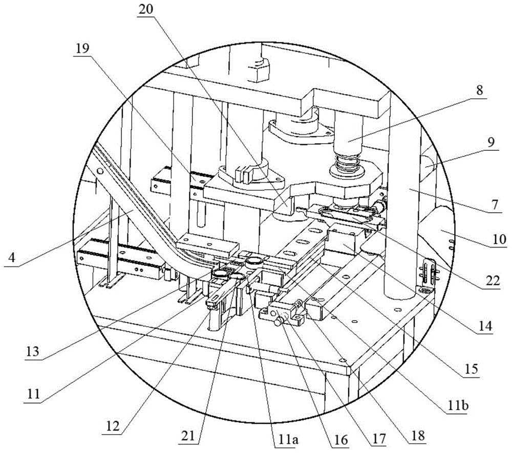
[0018] Such as Figure 1~Figure 4 As shown, the U-iron feeding and sorting mechanism is used to transport the U-iron 21 to the positioning fixture 14 in the U-iron basin frame translation mechanism in sequence; The iron material channel 4, the sorting guide block 11, the first pushing plate 12 and the second pushing plate 13 are composed, the vibrating material frame 2 is arranged on the side of the machine platform 1, and the vibrating ...


PUM


Abstract

The invention relates to an automatic riveting apparatus of loudspeaker U iron and a basin stand. A U iron feeding sorting mechanism is used for sequentially conveying the U iron to a positioning clamp in a U iron basin stand translation mechanism. The U iron basin stand translation mechanism is used for sending the U iron and the basin stand to a stamping position below a stamping mechanism. The stamping mechanism is used for riveting the U iron and the basin stand together, wherein the U iron and the basin stand are sent to the stamping position. A finished product charging conduit is installed on a machine stand. A feed inlet of the finished product charging conduit is located in front of the stamping position of the stamping mechanism. A finished product material pushing mechanism is arranged right behind the stamping position of the stamping mechanism. The finished product material pushing mechanism is used for pushing the U iron and the basin stand which form interference riveting into the feed inlet of the finished product charging conduit. The structure is ingenious and reasonable. The basin stand and the U iron can be automatically stamped and riveted according to a program. Labor difficulty and intensity of operation personnel are effectively reduced. An assembling qualified rate and production efficiency are increased. An injury risk of operator hands below a stamping head is avoided.

Description

technical field [0001] The invention relates to an automatic riveting device for a loudspeaker U iron and a pot frame, belonging to the technical field of loudspeaker assembly. Background technique [0002] As a sounding body, the speaker must be tightly combined with each other, otherwise the speaker will have abnormal sound or even be unusable. The installation of each component of the loudspeaker requires an accurate installation position and a firm connection between the components, especially the main component U-iron and the basin frame must be firmly combined. [0003] At present, the assembly of the speaker U iron and the pot frame is generally positioned with the help of a special fixture. First, the U iron is placed directly under the stamping head of the equipment, and then the basin frame is placed on the U iron, and the stamping head is used to start the equipment. Stamping directly below , so that the U-iron and the pot frame are riveted with interference, and...

Claims


Application Information

Patent Timeline
Patent Type & Authority Applications(China)
IPC IPC(8): H04R11/02
Inventor 蒋加星肖阳陈陆涛
Owner WUXI JIEFU ELECTROACOUSTIC
Why Eureka
Try Eureka