
Automatic glue brushing machine

An automatic brush and glue machine technology, applied in the direction of coating, the device for coating liquid on the surface, etc., can solve the problems of increasing the labor difficulty of operators, increasing the labor intensity of workers, slow glue brushing, etc., and achieves a simple structure. , The effect of low production cost and easy cleaning

Inactive Publication Date: 2018-05-04
常州晗业智能科技有限公司
View PDF0 Cites 1 Cited by
  • Summary
  • Abstract
  • Description
  • Claims
  • Application Information

AI Technical Summary

Problems solved by technology

[0003] There are the following problems in the automatic glue brushing machine of the prior art: 1, the structure of the automatic glue brushing machine is complex at present, the manufacturing cost is high, and the price is expensive, causing some small and medium-sized enterprises and factories to still use the traditional manual glue brushing method for production. The processing method increases the labor intensity of the workers, and at the same time, the glue is not uniform, and the speed of glue brushing is slow, which affects the quality of the product; 2. After the existing automatic glue brushing machine is completed, a large amount of residual glue will remain on the work surface , in order to avoid the residual glue affecting the next operation, most of the residual glue on the work surface needs to be cleaned up. The existing cleaning is almost done by manual or semi-automatic methods. Since each manual operation is different, manual inspection must be carried out, which is a waste of time. At the same time, it increases the labor difficulty of the operator

Method used


Image

  • Automatic glue brushing machine
  • Automatic glue brushing machine
  • Automatic glue brushing machine

Examples


Embodiment Construction

[0020] The following will clearly and completely describe the technical solutions in the embodiments of the present invention with reference to the accompanying drawings in the embodiments of the present invention. Obviously, the described embodiments are only some, not all, embodiments of the present invention. Based on the embodiments of the present invention, all other embodiments obtained by persons of ordinary skill in the art without making creative efforts belong to the protection scope of the present invention.

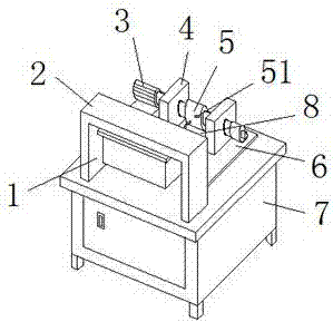
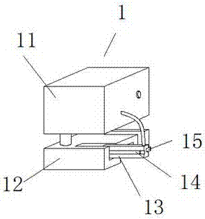
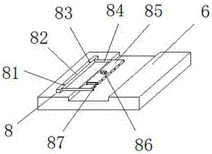
[0021] see Figure 1-3 , the present invention provides the following technical solutions: an automatic gluing machine, comprising a gluing mechanism 1, a frame 7 and a residual glue removal mechanism 8, one side of the frame 7 is provided with a first bracket 2, and the other side of the frame 7 One side is provided with a workbench 6, and the middle position of the workbench 6 is provided with a groove for workpieces to be processed. The left and right sides...


PUM


Abstract

The invention discloses an automatic glue brushing machine, which comprises a glue aligning mechanism, a machine frame and a residue glue clearing mechanism, wherein a first support frame is arrangedat one side of the machine frame; a work table is arranged at the other side of the machine frame; the glue aligning mechanism is arranged under the first support frame; second support frames are symmetrically arranged at the left side and the right side above the work table; a rotating shaft is arranged at one side of the second support frame; the residue glue clearing mechanism is arranged at the other side of the second support frame; a glue brushing round wheel is arranged at the outer part of the rotating shaft. The glue is brushed onto a workpiece to be processed through a glue brushinground wheel structure; a glue water thickness detection sensor structure monitors the thickness of glue water on the surface of the glue brushing round wheel in real time, so that the glue dischargingfrom a glue discharging pipe can be timely controlled; the fully automatic glue brushing production is realized; the work intensity of workers is reduced; the production efficiency is greatly improved; the structure is simple; the design is reasonable; the manufacturing cost is low; the automatic glue brushing machine is applicable to medium-small-sized enterprise and factory production.

Description

technical field [0001] The invention belongs to the technical field of mechanical equipment, and in particular relates to an automatic glue brushing machine. Background technique [0002] In recent years, with the reform of production and technology, mechatronics has developed greatly. Automatic brushing machines have been widely used in the assembly and maintenance of mechanical equipment in my country. Although with the rapid development of modern technology, automatic brushing machines The production process of the glue machine is gradually becoming mature, but there are still some deficiencies to be improved. [0003] There are the following problems in the automatic glue brushing machine of the prior art: 1, the structure of the automatic glue brushing machine is complex at present, the manufacturing cost is high, and the price is expensive, causing some small and medium-sized enterprises and factories to still use the traditional manual glue brushing method for producti...

Claims


Application Information

Patent Timeline
Patent Type & Authority Applications(China)
IPC IPC(8): B05C1/06B05C13/00B05C11/02B05C11/10
CPCB05C1/06B05C11/02B05C11/1002B05C11/1039B05C13/00
Inventor 杨葛炎杨红炎
Owner 常州晗业智能科技有限公司
Learn More