Inkjet printer head
An inkjet print head and nozzle technology, applied in printing and other directions, can solve problems that have not yet received attention
- Summary
- Abstract
- Description
- Claims
- Application Information
AI Technical Summary
Problems solved by technology
Method used
Image

Examples
no. 1 approach
[0025] (structure)
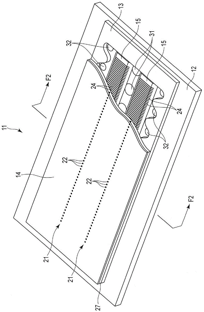
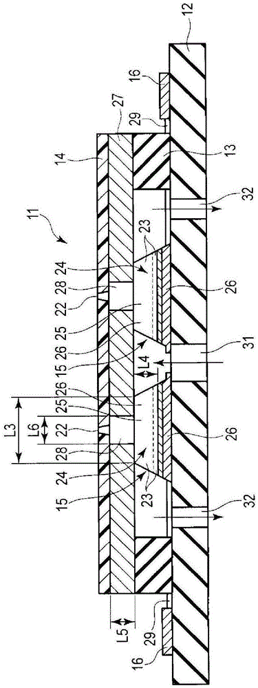
[0026] Figure 1 to Figure 5 (B1) to (B6) show the first embodiment of the present invention. The inkjet head 11 of the present embodiment is an inkjet head of a so-called shear mode shared wall method and an ink circulation type, and has a structure called a side jet type. like figure 1 and figure 2 As shown, the inkjet head 11 has: a substrate 12, a frame member 13 bonded to the substrate 12, a nozzle plate 14 bonded to the frame member 13, and a piezoelectric nozzle bonded to the substrate 12 at a position inside the frame member 13. Component 15 and IC 16 for driving the nozzle head for driving the piezoelectric component 15 .
[0027] The nozzle plate 14 is formed of a rectangular polyimide film. The nozzle plate 14 has a pair of nozzle rows 21 . Each nozzle row 21 includes a plurality of nozzles 22 .
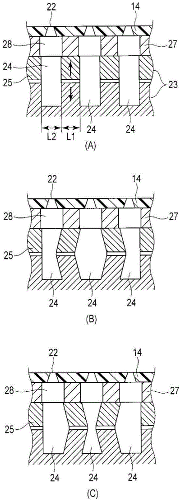
[0028] The piezoelectric member 15 is formed by bonding, for example, two piezoelectric plates 23 made of PZT (lead zirconate titanate) so tha...
no. 2 approach
[0055] (structure)
[0056] Figure 6 to Figure 10 (B1) to (B6) show the second embodiment of the present invention. The same code|symbol is attached|subjected to the same part as 1st Embodiment. The inkjet head 11 of the present embodiment is an inkjet head of a so-called shear mode shared wall method and an ink circulation type, and has a structure called a side jet type. Such as Figure 6 and Figure 7 As shown, the inkjet head 11 has: a substrate 12, a frame member 13 bonded to the substrate 12, a nozzle plate 14 bonded to the frame member 13, and a piezoelectric nozzle bonded to the substrate 12 at a position inside the frame member 13. Component 15 and IC 16 for driving the nozzle head for driving the piezoelectric component 15 .
[0057] The nozzle plate 14 is formed of a resin material having a thickness of 25 μm to 75 μm, for example, a rectangular polyimide film. The nozzle plate 14 has a pair of nozzle rows 21 . Each nozzle row 21 includes a plurality of nozz...
no. 3 approach
[0089] (structure)
[0090] Figure 11 to Figure 15 (B1)-(B6) show the 3rd embodiment of this invention. The same code|symbol is attached|subjected to the same part as 1st and 2nd embodiment. The inkjet head 11 of the present embodiment is an inkjet head of a so-called shear mode shared wall method and an ink circulation type, and has a structure called a side jet type. like Figure 11 and Figure 12 As shown, the inkjet head 11 has: a substrate 12, a frame member 13 bonded to the substrate 12, a nozzle plate 14 bonded to the frame member 13, and a piezoelectric nozzle bonded to the substrate 12 at a position inside the frame member 13. Component 15 and IC 16 for driving the nozzle head for driving the piezoelectric component 15 .
[0091] The nozzle plate 14 is formed of a resin material having a thickness of 25 μm to 75 μm, for example, a rectangular polyimide film. The nozzle plate 14 has a pair of nozzle rows 21 . Each nozzle row 21 includes a plurality of nozzles 2...
PUM
 Abstract
Description
Claims
Application Information
 - R&D Engineer
- R&D Manager
- IP Professional
- Industry Leading Data Capabilities
- Powerful AI technology
- Patent DNA Extraction
Browse by: Latest US Patents, China's latest patents, Technical Efficacy Thesaurus, Application Domain, Technology Topic.
© 2024 PatSnap. All rights reserved.Legal|Privacy policy|Modern Slavery Act Transparency Statement|Sitemap