Electronic endoscope battery section

a battery section and electronic endoscope technology, applied in the field of electronic endoscopes, can solve the problems of inconvenient operation, troublesome removal and change of operation switches, and inability to accurately detect the remaining battery power of electronic endoscopes, and achieve excellent usability

Inactive Publication Date: 2009-11-10
FUJI PHOTO OPTICAL CO LTD
View PDF16 Cites 544 Cited by
  • Summary
  • Abstract
  • Description
  • Claims
  • Application Information

AI Technical Summary

Benefits of technology

[0011]An object of the present invention is to provide an electronic endoscope that corresponds with actual use and has excellent usability.
[0015]According to the present invention, the battery section has the memory rewritable of data. For this configuration, it is possible to store the charging time and the number of charging of the battery, and the customized information in which the functions to be assigned to the plural operating members are specified in the memory. Therefore, the electrical endoscope that corresponds with the actual use and has excellent usability can be provided.

Problems solved by technology

Therefore, when the operation switch is fixed to one function as usual, it is sometimes inconvenient depending on the region to be inspected or the operator.
Therefore, the electronic endoscope cannot accurately detect the remaining battery power when used with several batteries exchanged thereon.
In the electronic endoscope disclosed in the Japanese Patent Laid-Open Publication No.2003-275162, it is troublesome to remove and change the operation switches, and there is a risk that the operation switch may be lost when removed from the attachment portion.
In the electronic endoscope disclosed in the Japanese Patent Laid-Open Publication No.2003-275174, a space for providing the rotary switch is required, so there is a problem that the article becomes large in dimension.
Additionally, the combination of the operation switch and the function capable of being set and changed is limited.

Method used


Image

  • Electronic endoscope battery section
  • Electronic endoscope battery section
  • Electronic endoscope battery section

Examples


Embodiment Construction

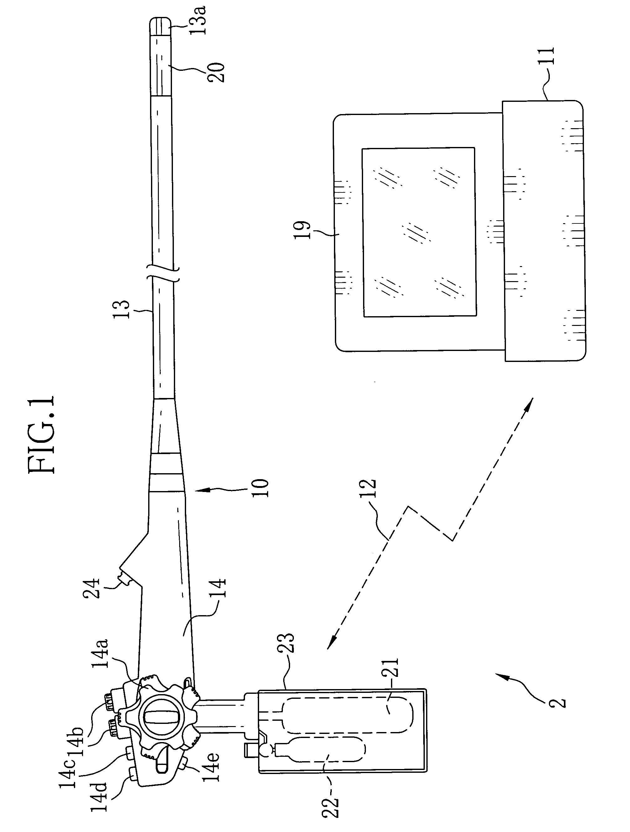
[0023]In FIG. 1, an electronic endoscope apparatus 2 is constituted of an electronic endoscope 10 and a processor device 11. The electronic endoscope 10 exchanges the signals with the processor device 11 by an electric wave 12.

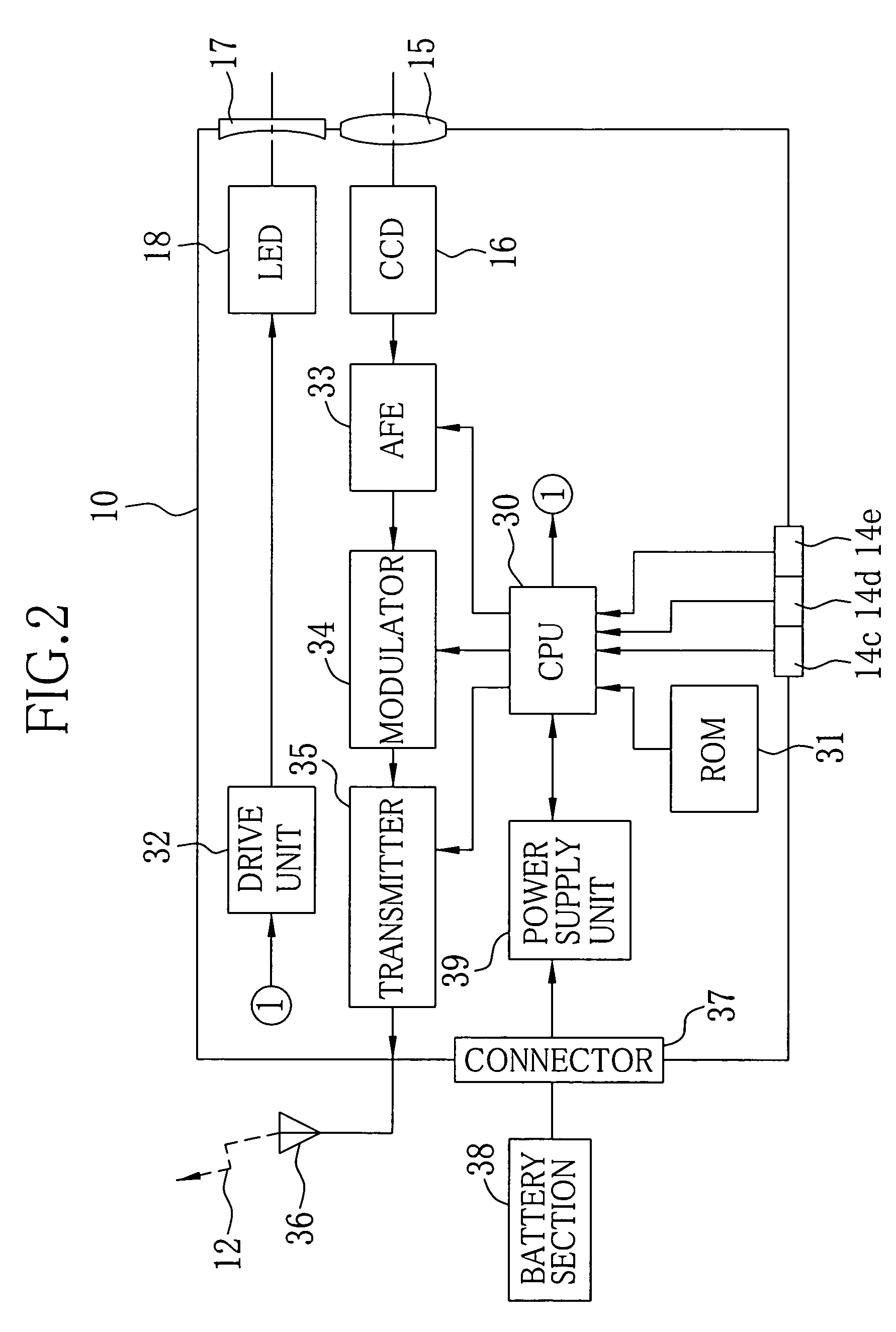
[0024]The electronic endoscope 10 is provided with an insertion section 13 inserted into a body cavity and an operation section 14 connected to a base end portion of the insertion section 13. An objective lens 15, a CCD 16, an illumination lens 17 and an LED light source (hereinafter, LED) 18 (see FIG. 2) are built in a front end portion 13a provided at a front end of the insertion section 13. The objective lens 15 is for taking image light of a region to be inspected inside the body cavity. The CCD 16 is an imaging element for photographing images of the region to be inspected inside the body cavity. The LED 18 is for illuminating inside the body cavity. The image in the body cavity obtained by the CCD 16 is displayed as an endoscopic image on a monitor 19 co...


PUM

PropertyMeasurementUnit
frequency bandaaaaaaaaaa
rated voltageaaaaaaaaaa

Abstract

A battery section of an electronic endoscope is provided with an EEPROM. The EEPROM stores charging time and the number of charging of batteries, necessary for calculating remaining power of the batteries, and customized information for assigning functions to first, second and third switches of an operation section. A remaining-power calculator calculates the remaining power of the batteries based on a relation between discharge voltage and discharge time of the batteries as well as on the charging time and the number of charging of the batteries read out from the EEPROM. A function assignment circuit assigns the functions to the first, second and third switches in accordance with the customized information read out from the EEPROM.

Description

BACKGROUND OF THE INVENTION[0001]1. Field of the Invention[0002]The present invention relates to an electronic endoscope having a battery that supplies electric power.[0003]2. Description of the Related Arts[0004]Medical diagnoses using an electronic endoscope are widely performed. The electronic endoscope has a built-in imaging device such as a CCD at a front end of an insertion section, which is inserted into a body cavity. A processor device applies signal processing to the imaging signals obtained with the CCD, and the image inside of the body cavity (endoscopic image) can be observed on a monitor.[0005]As one type of the electronic endoscopes, there is a so-called battery-powered electronic endoscope having a battery that supplies electric power (see Japanese Patent Laid-Open Publication No.2001-166222). The battery-powered electronic endoscope described in the above publication is provided with a charging circuit for changing the battery, a counter for counting the number of c...

Claims


Application Information

Patent Timeline
Patent Type & Authority Patents(United States)
IPC IPC(8): A61B1/00H01M50/202
CPCA61B1/00016A61B1/00034A61B1/05H01M10/44A61B2560/0214H01M2/1022A61B2017/00734Y02E60/10H01M50/202
Inventor ABE, KAZUNORI
Owner FUJI PHOTO OPTICAL CO LTD
Why Eureka
Try Eureka