Glass automatic processing equipment

A technology for automatic glass processing, applied in glass manufacturing equipment, glass molding, glass reshaping, etc., can solve the problems of high processing cost of single cup, uneven thickness of cup wall, low production efficiency, etc., to reduce processing Probability of occurrence of defects, standardization of work flow, and effect of improving work efficiency

Active Publication Date: 2015-10-14
徐州博创建设发展集团有限公司
View PDF5 Cites 8 Cited by
  • Summary
  • Abstract
  • Description
  • Claims
  • Application Information

AI Technical Summary

Problems solved by technology

[0002] At present, there are two main methods of making single-layer glass. One is the film pressing method, which uses heavy stamping to force the high-temperature glass liquid to form in the mold. This method of production requires a matching kiln to heat the glass. To the molten state, the requirements for related equipment are relatively high, the finished product is buckled unevenly, the buckle, the roundness of the cup body is not enough, the surface of the cup body is often dirty, and the transparency is poor; the other is the blown film method, which uses the pressure of air pressure Shape molten glass in a mold
This production method is complicated in process and low in efficiency. In addition to high requirements for supporting kilns and related equipment, it also requires high levels of work for specific operators; Thin and uneven wall thickness, poor transparency of finished product
These two methods have the problems of low production efficiency, high processing cost per cup, poor transparency of finished products, and high requirements for production environment supporting facilities.

Method used


Image

  • Glass automatic processing equipment
  • Glass automatic processing equipment
  • Glass automatic processing equipment

Examples


Embodiment approach

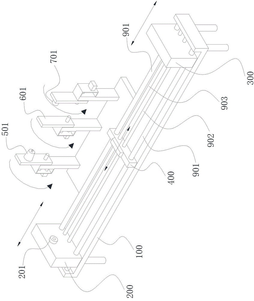
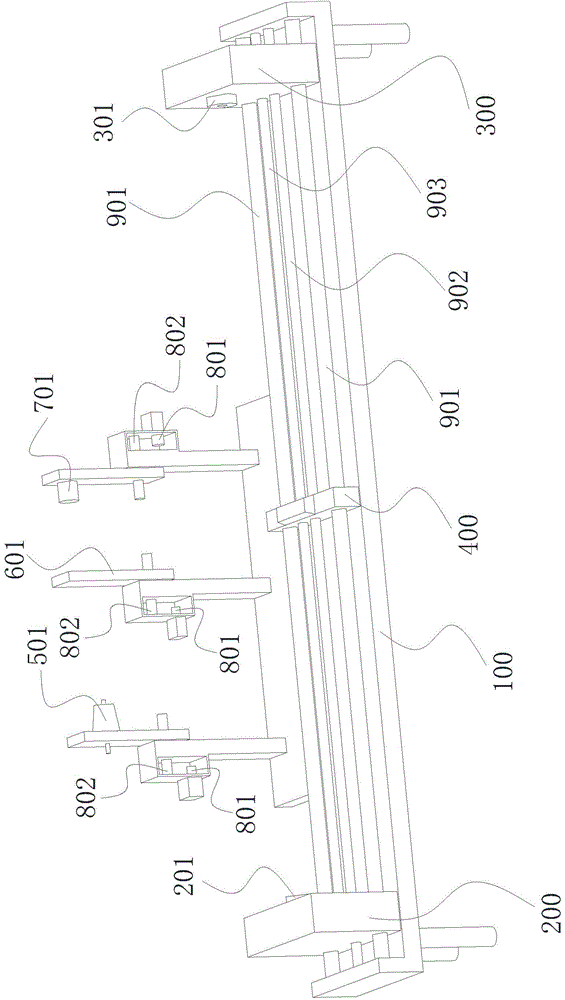
[0031] Such as Figure 1-Figure 4 As shown, the glass automatic processing equipment includes a frame 100, a front-end rotating device 200, a rear seat, a heating device, a pressing plate 601, a thread rolling wheel 701 and a controller, wherein:

[0032] The front-end rotating device 200 is rotatably installed on the frame 100 and its rotation is driven by the first power unit and the first transmission unit connected to it. The front-end rotating device 200 includes a first clamping end of the glass tube from the peripheral side. A clamping mechanism 201, the first clamping mechanism 201 fixes the glass tube on it by fixing one end of the glass tube, and makes the glass tube rotate around its axis under the drive of the first power unit and the first transmission unit;

[0033] The rear seat is slidably mounted on the frame 100 along the direction approaching / away from the front-end rotating device 200 under the drive of the third power unit and the third transmission unit c...


PUM


Abstract

The invention discloses glass automatic processing equipment. The equipment comprises a rack, a front end rotating device, a rear base, a rear end rotating device, a heating device, pressing plates, a thread rolling wheel and a plurality of detection units, wherein the front end rotating device is installed on the rack in a rotatable manner; the rear base is installed on the rack in a slidable manner; the rear end rotating device is installed on the rear base in a rotatable manner; the heating device is arranged between the front end rotating device and the rear end rotating device and is installed on the rack in a slidable manner; the pressing plates and the thread rolling wheel are installed on the rack in a turnover manner. The equipment has the beneficial effects that through synchronous rotation of the front end rotating device and the rear end rotating device, glass tubes are clamped between a first clamping mechanism and a second clamping mechanism; the parts, needing to be processed, of the glass tubes, are in a molten state by adopting the heating device; the glass tubes are necked down by being pressed by the pressing plates, so that the glass tubes are easy to break from the necks; the thread rolling wheel rolls at openings of glasses, so that the openings of the glasses are in a necking down state and threads are formed on the outer walls of the openings through rolling.

Description

technical field [0001] The invention relates to a glass cup processing equipment, in particular to a glass cup automatic processing equipment. Background technique [0002] At present, there are two main methods of making single-layer glass. One is the film pressing method, which uses heavy stamping to force the high-temperature glass liquid to form in the mold. This method of production requires a matching kiln to heat the glass. To the molten state, the requirements for related equipment are relatively high, the finished product is buckled unevenly, the buckle, the roundness of the cup body is not enough, the surface of the cup body is often dirty, and the transparency is poor; the other is the blown film method, which uses the pressure of air pressure The molten glass is shaped in a mold. This production method is complicated in process and low in efficiency. In addition to high requirements for supporting kilns and related equipment, it also requires high levels of work...

Claims


Application Information

Patent Timeline
Patent Type & Authority Applications(China)
IPC IPC(8): C03B23/045
Inventor 孔德训
Owner 徐州博创建设发展集团有限公司
Why Eureka
Try Eureka