Novel lift check valve

A lift type, check valve technology, applied in the direction of control valves, valve devices, functional valve types, etc., can solve the problems of poor sealing performance between the valve body and the valve disc, slow valve opening and closing speed, and reduced service life. Good performance, rapid opening and closing, and the effect of reducing water pressure

Inactive Publication Date: 2015-10-14
SUZHOU KEDI FLUID CONTROL EQUIP
View PDF8 Cites 5 Cited by
  • Summary
  • Abstract
  • Description
  • Claims
  • Application Information

AI Technical Summary

Problems solved by technology

However, due to the structural defects of the traditional check valve, the opening and closing speed of the valve is slow, which makes the water hammer pressure high. At the same time, the sealing performance between the valve body and the disc is poor, which seriously affects the efficacy of the entire valve and reduces the service life.

Method used


Image

  • Novel lift check valve
  • Novel lift check valve

Examples


Embodiment 1

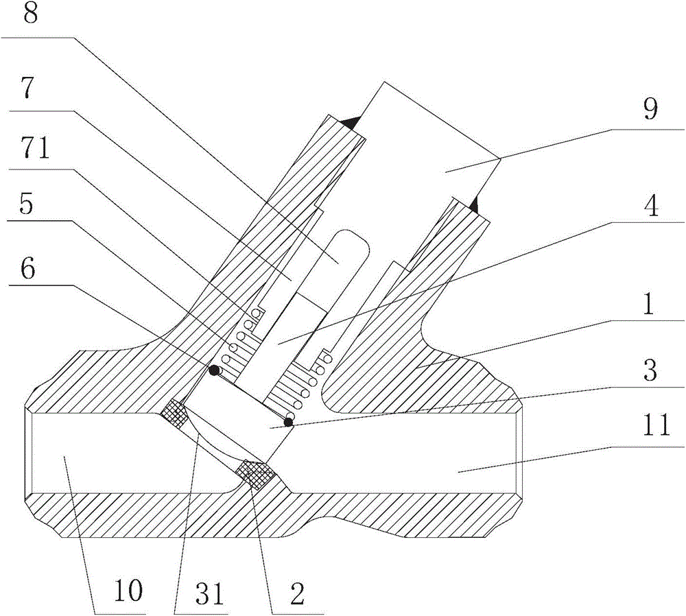
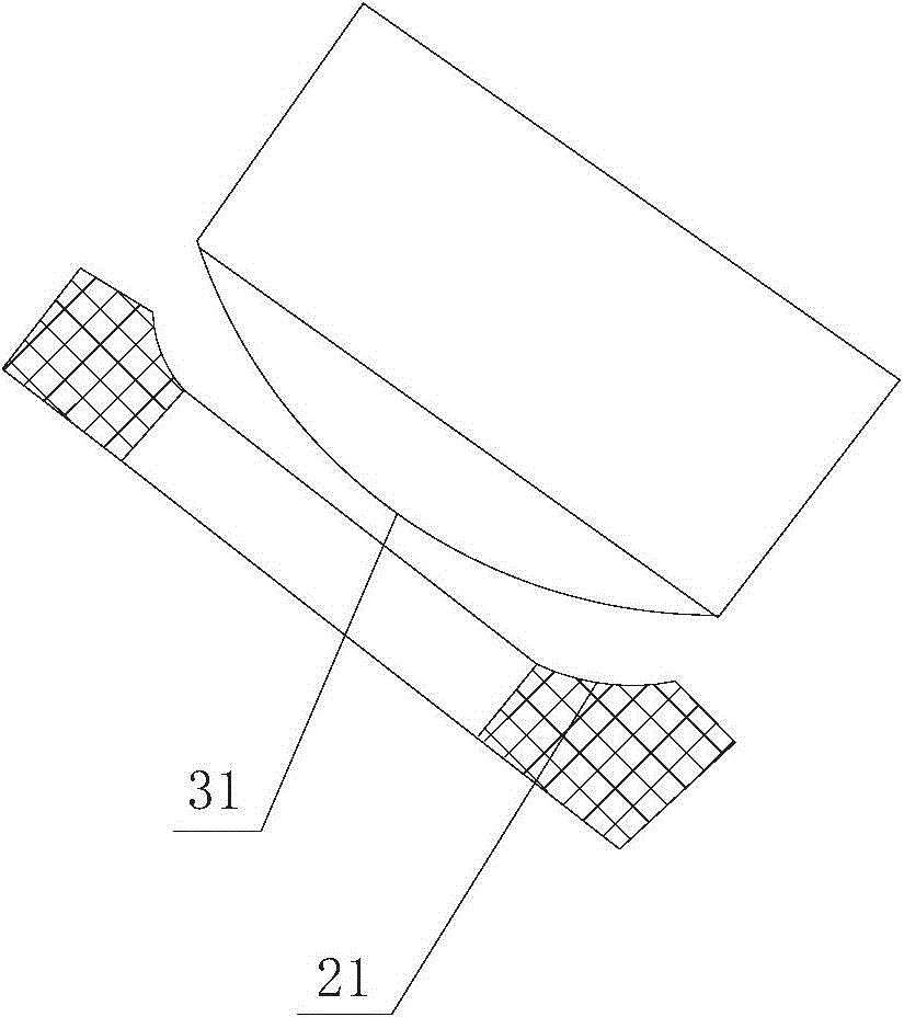
[0019] Such as figure 1 , figure 2 As shown, a new lifting check valve includes a valve body 1, a valve seat 2, a valve disc 3 and a valve stem 4, and the valve seat 2, valve disc 3 and valve stem 4 are all arranged inside the valve body 1; the valve disc One end of 3 is connected to the valve stem 4, and the other end is connected to the valve seat 2. The new lift check valve also includes a self-sealing device, which includes a spring 5, a collar 6 and a guide shaft 7, the spring 5, the collar 6 and The guide shaft 7 is sheathed upwards on the valve stem 4 sequentially from the joint between the valve disc 3 and the valve stem 4 ; a cavity 8 is provided inside the guide shaft 7 to make the valve stem 4 move back and forth in the cavity 8 . Along the axial direction of the guide shaft 7 , the length of the cavity 8 is not greater than the length of the valve stem 4 .

[0020] The lower end of the guide shaft 7 is provided with a stepped surface 71 along its circumference a...

Embodiment 2

[0023] The rest are the same as the above-mentioned embodiment, the difference is that, as figure 1 As shown, the new lifting check valve also includes a bonnet 9 threadedly connected to the valve body 1, and the bonnet 9 is welded together with the external connection of the valve body 1, so that the valve is in a sealed state and completely isolated from the outside world. One end of the guide shaft 7 is connected to the valve cover 9, and the guide shaft 7 and the valve cover 9 are integrally structured.

Embodiment 3

[0025] The rest are the same as the above-mentioned embodiment, the difference is that, as figure 1 As shown, the valve flap 3 and the valve stem 4 are of an integral structure.


PUM


Abstract

Disclosed is a novel lift check valve. The novel lift check valve comprises a valve body, a valve seat, a valve clack and a valve rod. The valve seat, the valve clack and the valve rod are arranged inside the valve body. One end of the valve clack is connected with the valve rod, and the other end of the valve clack is connected with the valve seat. The novel lift check valve further comprises a self-sealing device. The self-sealing device comprises a spring, a lantern ring and a guide shaft, wherein the spring, the lantern ring and the guide shaft are arranged on the valve rod in sequence from the position of connection between the valve clack and the valve rod to the top in a sleeving mode. A cavity is arranged inside the guide shaft so that the valve rod can move back and forth in the cavity. By the adoption of the novel lift check valve, due to the fact that the self-sealing device is arranged, the valve clack and the valve seat can be rapidly opened and closed through the pressure difference of fluid, the sealing performance is good in the closing process, and backflow of the fluid is prevented in time. Meanwhile, the pressure of a water hammer can be reduced, and the service life of the novel lift check valve is prolonged.

Description

technical field [0001] The invention relates to a check valve, in particular to a novel lifting check valve. Background technique [0002] A check valve is a valve that automatically prevents fluid from flowing backwards. The opening and closing parts are opened under the action of fluid pressure, and the fluid flows from the inlet side to the outlet side. When the pressure on the inlet side is lower than that on the outlet side, the disc will automatically close under the action of factors such as fluid pressure difference and its own gravity to prevent the fluid from flowing backward. Therefore, the check valve is also called "one-way valve", "reverse flow valve" and so on. Due to the simple effect and low cost of the check valve, the check valve is widely used in power plants, chemical industry, food, pharmaceutical and other industries. However, due to the structural defects of the traditional check valve, the opening and closing speed of the valve is slow, resulting ...

Claims


Application Information

Patent Timeline
Patent Type & Authority Applications(China)
IPC IPC(8): F16K15/06
CPCF16K15/06
Inventor 田洪卫
Owner SUZHOU KEDI FLUID CONTROL EQUIP
Why Eureka
Try Eureka