A Piezoelectric Force Measuring Device with Small Range and Large Range Ratio

A force-measuring device and a small-range technology, which is applied to the measurement of the force of the piezoelectric device, can solve the problem that the range of the lateral vector force cannot be adjusted, and achieve the effect of simple structure, convenient and flexible process, and easy packaging

Active Publication Date: 2017-04-12
DALIAN UNIV OF TECH
View PDF6 Cites 0 Cited by
  • Summary
  • Abstract
  • Description
  • Claims
  • Application Information

AI Technical Summary

Problems solved by technology

[0007] The technical problem to be solved by the present invention is to change the difficult problem that the main and lateral vector force ranges of the traditional multi-dimensional piezoelectric test device cannot be adjusted, and to invent a small-range and large-range-ratio test device with an adjustable range function

Method used


Image

  • A Piezoelectric Force Measuring Device with Small Range and Large Range Ratio
  • A Piezoelectric Force Measuring Device with Small Range and Large Range Ratio
  • A Piezoelectric Force Measuring Device with Small Range and Large Range Ratio

Examples


Embodiment Construction

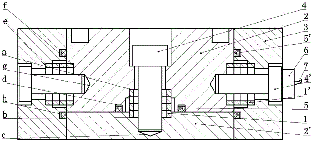
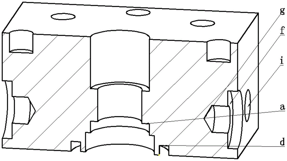
[0021] The implementation of the present invention will be described in detail in conjunction with the technical scheme and accompanying drawings. Such as figure 2 , 3 As shown, the upper positioning groove a, the main seal ring positioning hole d, the main pressure plate side positioning groove f, the lead joint installation hole i, and the side bolt hole g are respectively processed on the upper platen 2 to ensure the contact surface and side positioning of the upper positioning groove a. The surface roughness and smoothness of the contact surface of the groove f facilitate the accurate positioning of the X0 piezoelectric cut crystal group 1 in the main direction and the four Y0 piezoelectric cut crystal groups 1' in the lateral direction. The lower positioning groove b and the main bolt hole c are respectively processed on the lower pressing plate 2' to ensure the surface roughness and smoothness of the contact surface of the lower positioning groove b, so as to facilitat...


PUM


Abstract

The invention discloses a piezoelectric small-range large-range ratio force-measuring device, which comprises piezoelectric crystal groups, fastening bolts, a pressure plate, sealing rings and a lead joint. The piezoelectric crystal groups serve as force-sensing elements and have the characteristics of high sensitivity, high stiffness and high natural frequency, and requirements of a high-precision test can be met. One X0 piezoelectric crystal group is arranged in the main direction, the other four Y0 crystal groups are arranged in two lateral directions, and thus vector forces in the main direction and the lateral directions are tested respectively. The fastening bolts are used for preloading piezoelectric crystal plates in the main direction and the lateral directions, the preloading force and a lateral force range can be adjusted, and the difficulty of testing a large range ratio of the main direction force and the lateral direction force can be solved. Due to the design of a two-way push-pull structure, influences on the test precision by outside temperature changes can be avoided. The test device has the advantages that the structure is simple, packaging is convenient, adjustment is convenient, and high-precision three-dimensional dynamic force test can be realized.

Description

technical field [0001] The invention belongs to the field of sensors and their measurement and control, and relates to the application of piezoelectric sensors in three-dimensional force testing. The piezoelectric quartz is used as the force-sensing element, and the bolts are used to adjust the pre-tightening force and range, which effectively meets the requirements of large range ratio of main and side force vectors, and can be applied to the occasion of dynamic measurement of three-dimensional force with small range and large range ratio. Background technique [0002] Thrust is an important parameter of rocket engine performance index, which directly reflects the working performance of the engine, so it is of great value to realize accurate dynamic force measurement. Due to the order of magnitude difference between the main thrust and the lateral thrust in the thrust test, the small lateral range is seriously interfered by the large main range, which restricts the improvem...

Claims


Application Information

Patent Timeline
Patent Type & Authority Patents(China)
IPC IPC(8): G01L1/16
Inventor 贾振元张军田雨任宗金刘巍
Owner DALIAN UNIV OF TECH
Why Eureka
Try Eureka