Fixed-wing aircraft operating force test sensor

A control force, fixed-wing aircraft technology, applied in the direction of measuring the force applied to the control element, etc., can solve the problems of difficult design work and measurement accuracy, difficulty in disassembly and test of the control force test sensor, etc., to improve the accuracy of test data, Easy to check and ensure the effect of structural strength

Active Publication Date: 2015-10-14
HARBIN
View PDF6 Cites 2 Cited by
  • Summary
  • Abstract
  • Description
  • Claims
  • Application Information

AI Technical Summary

Problems solved by technology

[0008] The technical problem to be solved by the present invention: in the traditional flight test, the difficulty of disassembling and testing the control force test sensor; the cross-linking error exists in each typ

Method used


Image

  • Fixed-wing aircraft operating force test sensor
  • Fixed-wing aircraft operating force test sensor
  • Fixed-wing aircraft operating force test sensor

Examples


Embodiment Construction

[0018] The installation and working methods of the present invention will be described below in conjunction with the accompanying drawings.

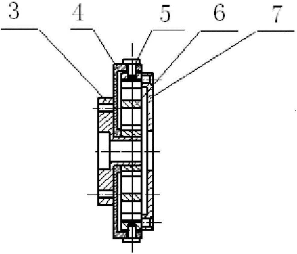
[0019] Such as figure 1 As shown: the sensor is composed of a lower mounting base 3, a base 4, a limit device 5, an elastic element 6, and an upper mounting base 7.

[0020] The base 4 and the elastic element 6 are connected by 8 bolts, the lower mounting base 3 and the base 4 are connected by 3 bolts, and the upper mounting base 7 and the elastic element 6 are connected by bolts, thus completing the assembly of the entire sensor.

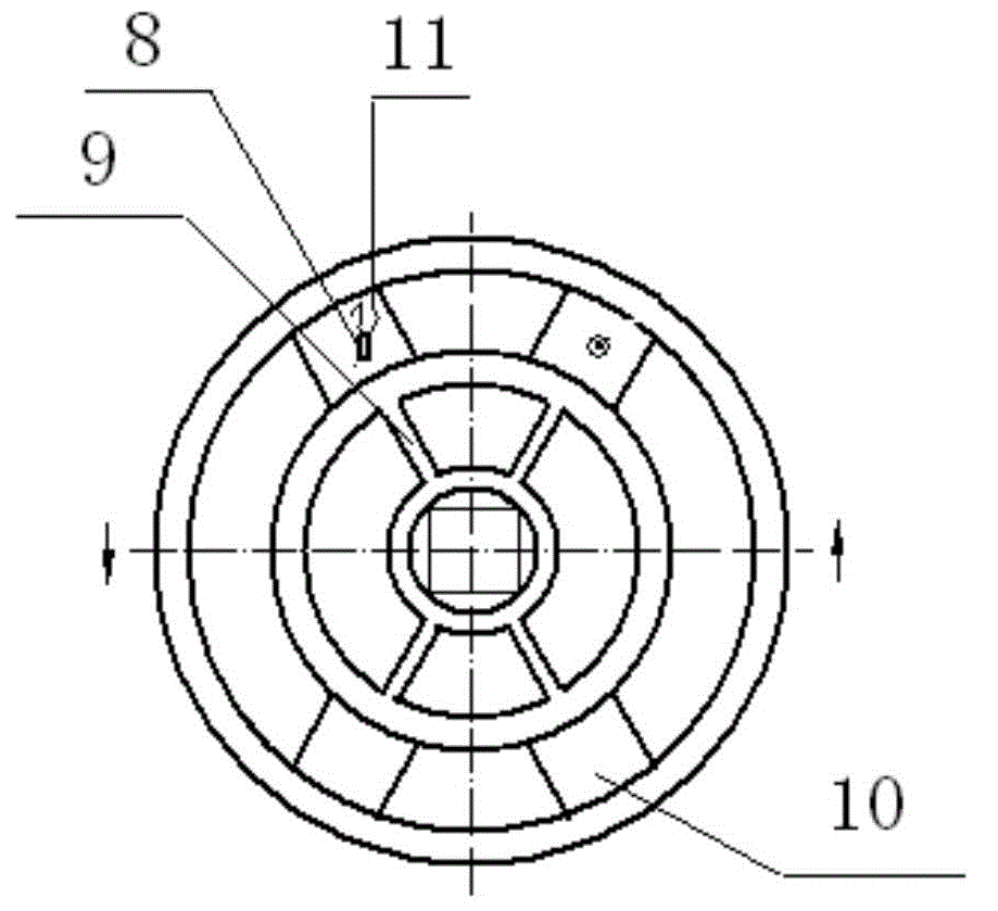
[0021] Such as figure 2 Shown is a schematic diagram of the elastic element structure.

[0022] The elastic element is the sensitive part of the disc force sensor and also the load-bearing part. There are many factors to choose the material of the elastic element. Considering the measurement accuracy of the sensor, structural strength, long-term output stability, etc., the quenched and tempered steel 40Cr...


PUM


Abstract

The invention relates to a fixed-wing aircraft operating force test sensor which comprises a change-over shaft (1), a sensor module (2) and an operating force conversion circuit. Change of stress is sensed by resistance strain gauges attacked to an elastic component, and electrical signals in proportion to the stress are formed; and after the electrical signals are subjected to signal conditioning through a convertor, voltage signals in proportion to the tested force are output, so that simultaneously-effective transverse strain force and longitudinal strain force of the operating force can be ensured, good reliability and maintainability are achieved, troubleshooting time in the flight test is saved, and data precision is improved.

Description

technical field [0001] The invention relates to a sensor for testing the maneuvering force of a fixed-wing aircraft, which belongs to the field of testing the maneuvering force of a flight test. Background technique [0002] There are two methods for the existing Y12 series aircraft to perform the control force test: [0003] 1. The test sensor is installed in the steering wheel and steering column system, destroying the internal structure of the system, and requires a horizontal sensor and a vertical sensor; [0004] 2. The test sensor is installed between the steering wheel and the steering column, but the influence of the cross-linking error is not eliminated. [0005] The disadvantages of existing testing methods are: [0006] 1. After the modification in the system, the sensor, the steering wheel and the steering column become a whole. The difficulty of troubleshooting during the test process increases, and the inspection and maintenance are relatively complicated; ...

Claims


Application Information

Patent Timeline
IPC IPC(8): G01L5/22
Inventor 崔秀娟宋静宇李继文温洪雷葛新
Owner HARBIN
Why Eureka
Try Eureka