Device and method for calibrating contact resistance tester

A technology of contact resistance and calibration devices, which is applied in the direction of measuring devices, instruments, measuring electrical variables, etc., can solve the problems of unable to calibrate the displayed value and cannot guarantee the calibration accuracy of the tester, and achieve the effect of improving the calibration accuracy

Inactive Publication Date: 2015-10-14
CRRC QINGDAO SIFANG CO LTD
View PDF8 Cites 11 Cited by
  • Summary
  • Abstract
  • Description
  • Claims
  • Application Information

AI Technical Summary

Problems solved by technology

The fixed value resistance is limited by the fixed value, and it is impossible to calibrate all the indications in the full range of the tester; although the sliding wire resistance method can achieve continuou

Method used


Image

  • Device and method for calibrating contact resistance tester
  • Device and method for calibrating contact resistance tester

Examples


Embodiment 1

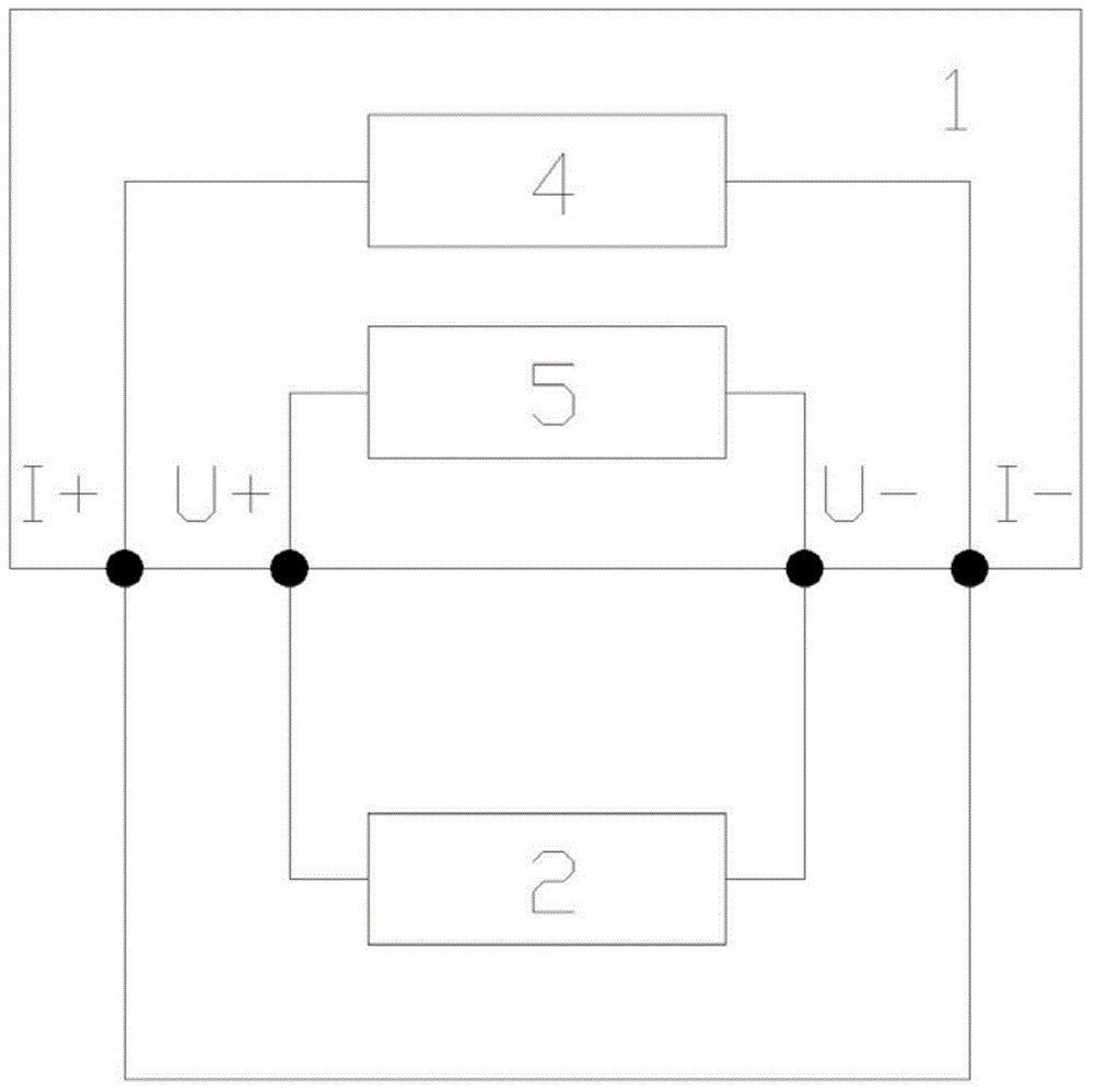
[0033] Such as figure 1 As shown, a contact resistance tester calibration device includes a contact resistance tester 1 under test, and a constant current source 4 and a voltmeter 5 are arranged inside the contact resistance tester 1 under test.

[0034] The output terminal of the constant current source 4 of the tested contact resistance tester 1 is connected to the positive pole and the negative pole, the voltage input terminal of the tested contact resistance tester 1 is connected to a standard voltage source 2, and the standard voltage source 2 is connected to the tested contact resistance tester 1 5 connections within the voltmeter.

[0035] Divide the voltage value of the standard voltage source 2 and the set value of the constant current source 4 according to Ohm's law to obtain the standard resistance value; the voltage detected by the internal voltmeter 5 of the contact resistance tester 1 and the setting of the constant current source 4 Value, divided according to O...

Embodiment 2

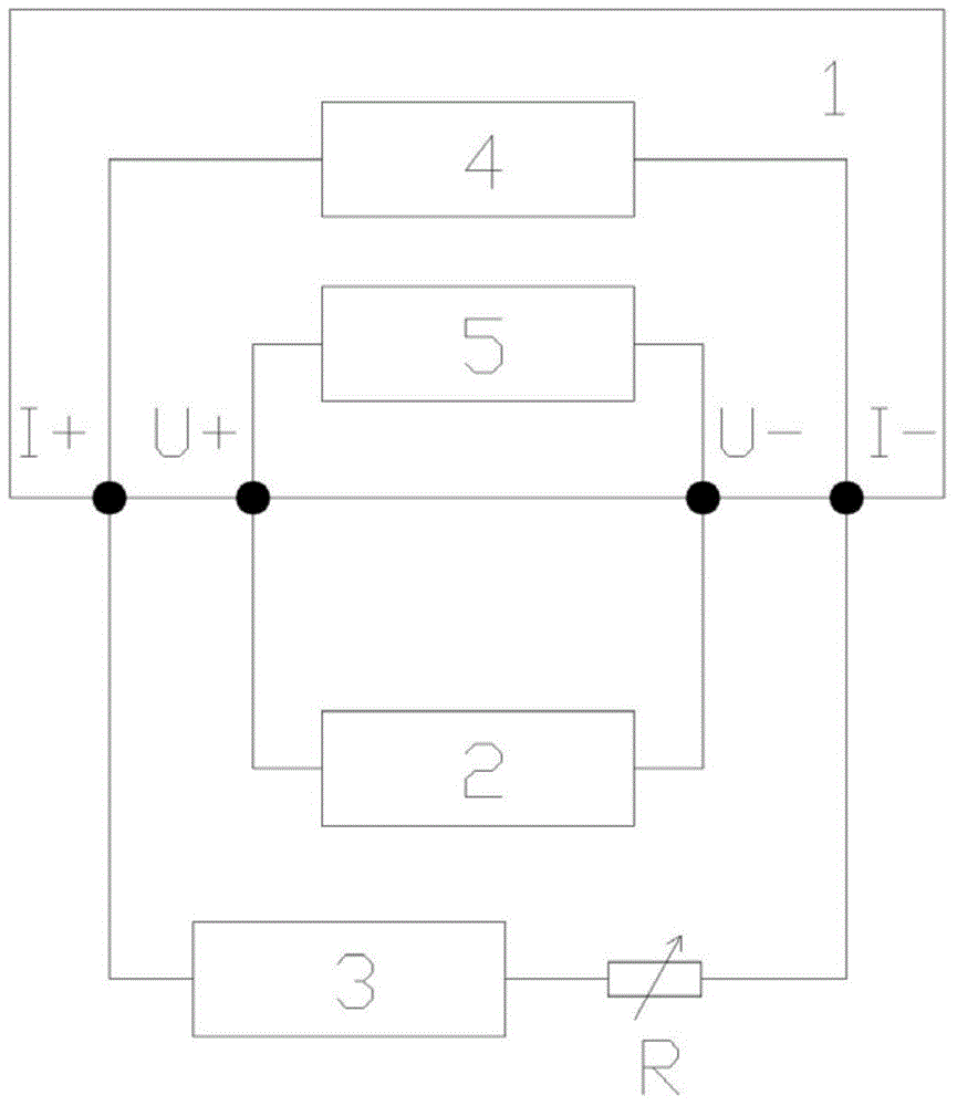
[0042] Compared with the first embodiment, this embodiment further eliminates the possibility of error caused by the constant current source 4 .

[0043] Such as figure 2 As shown, a contact resistance tester calibration device includes a contact resistance tester 1 under test, and a constant current source 4 and a voltmeter 5 are arranged inside the contact resistance tester 1 under test.

[0044] The output terminal of the constant current source 4 of the tested contact resistance tester 1 is connected to an ammeter 3, the voltage input terminal of the tested contact resistance tester 1 is connected to a standard voltage source 2, and the standard voltage source 2 is connected to the tested contact resistance tester 1. The voltmeter 5 is connected.

[0045] In order to protect the ammeter 3 from being damaged, a protective resistor is connected in series between the output terminal of the constant current source 4 of the contact resistance tester 1 and the ammeter 3, and t...


PUM


Abstract

The invention relates to a device and a method for calibrating a contact resistance tester. The device comprises a contact resistance tester. The positive electrode and the negative electrode of the output end of a constant-current source for the contact resistance tester are connected, or the output end of the constant-current source for the contact resistance tester is connected with an ammeter. The voltage input end of the contact resistance tester is connected with a voltage source. According to the technical scheme of the invention, a standard voltage source is set, and a standard resistance value calculated based on the ohm law is compared with the display value of the tester. In this way, the defect that not all resistance display values within the full measuring range of the contact resistance tester can be calibrated due to the limitation of fixed values provided by a fixed-value resistor is overcome. Meanwhile, the defect that the calibration precision of the tester cannot be ensured due to the limitation of the temperature coefficients of materials on a slide rheostat and the influence of the contact resistance of the sliding part of the rheostat can also be overcome. Therefore, the continuous adjustment and the point-by-point calibration are realized, and the calibration precision is improved.

Description

technical field [0001] The invention relates to a calibration device and method, in particular to a calibration device and method for a contact resistance tester. Background technique [0002] The high-speed train wheel set contact resistance tester is an important device for measuring the contact resistance of high-speed train wheel sets. Whether the contact between the wheel set and the axle meets the technical requirements is achieved by measuring the contact resistance of the wheel set. In order to ensure its measurement accuracy, its implementation of calibration is a necessary means. [0003] The calibration of the high-speed train wheel set contact resistance tester belongs to low-resistance calibration, which is particularly easy to introduce errors, and is usually carried out by fixed value resistance and sliding wire resistance method. The fixed value resistance is limited by the fixed value, and it is impossible to calibrate all the indications in the full range ...

Claims


Application Information

Patent Timeline
IPC IPC(8): G01R35/00
Inventor 曹戎高存丽
Owner CRRC QINGDAO SIFANG CO LTD
Why Eureka
Try Eureka