A Directional Output Ring Microcavity Laser

A laser and microcavity technology, applied in the field of annular microcavity lasers, can solve the problem of difficult coupling of light fields, and achieve good unidirectional effects

Inactive Publication Date: 2018-09-11
INST OF SEMICONDUCTORS - CHINESE ACAD OF SCI
View PDF6 Cites 0 Cited by
  • Summary
  • Abstract
  • Description
  • Claims
  • Application Information

AI Technical Summary

Problems solved by technology

The circular microcavity is a typical whispering gallery optical microcavity with a high quality factor, but the rotational symmetry of the circular optical microcavity makes the output of the light field is isotropic. This non-directional output makes Light field is difficult to effectively couple into free space to be utilized

Method used


Image

  • A Directional Output Ring Microcavity Laser
  • A Directional Output Ring Microcavity Laser
  • A Directional Output Ring Microcavity Laser

Examples


Embodiment Construction

[0029] In order to make the object, technical scheme and advantages of the present invention clearer, below in conjunction with specific embodiment, and refer to Figure 1-Figure 6 Shown, the present invention is further described in detail.

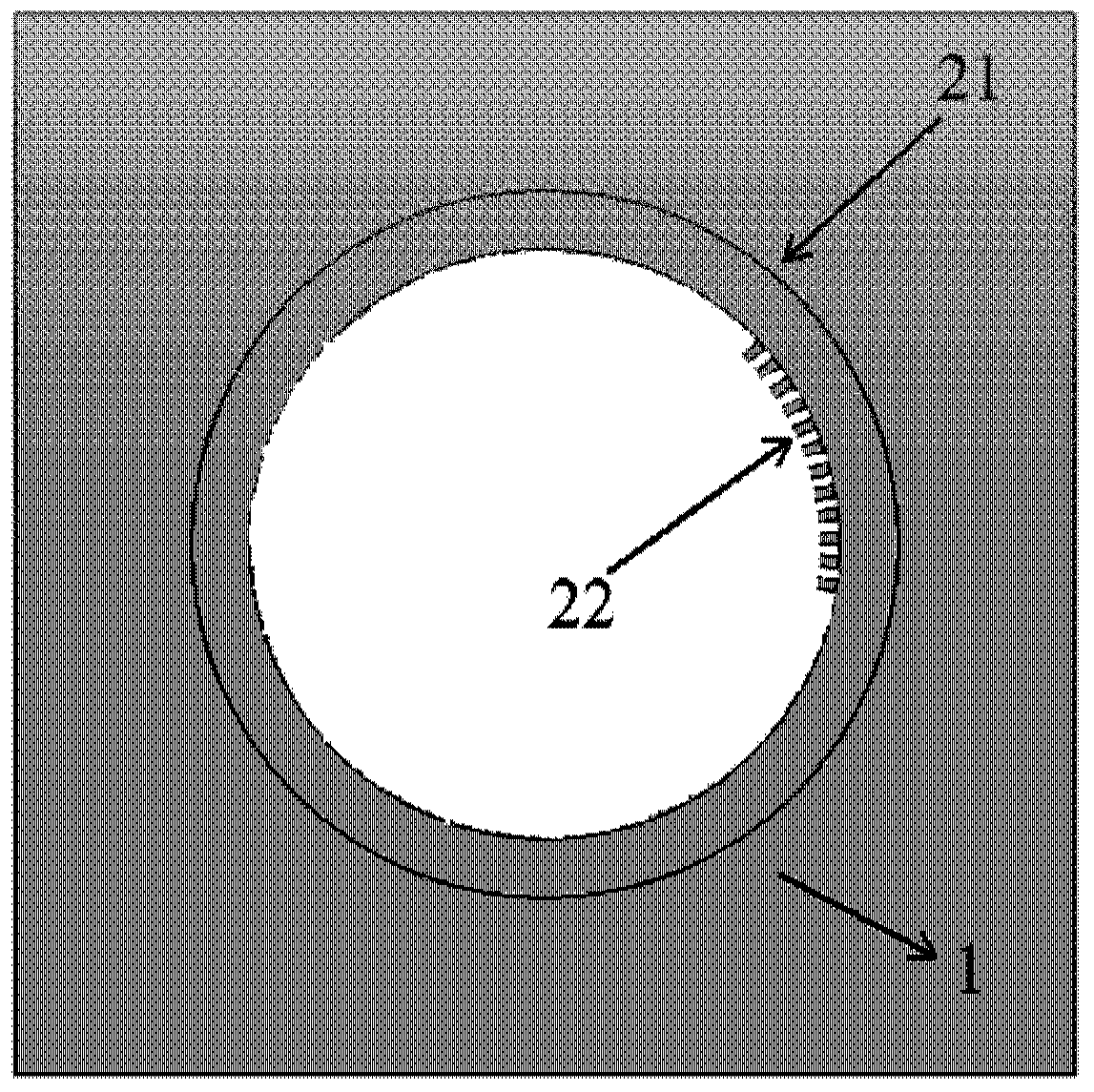
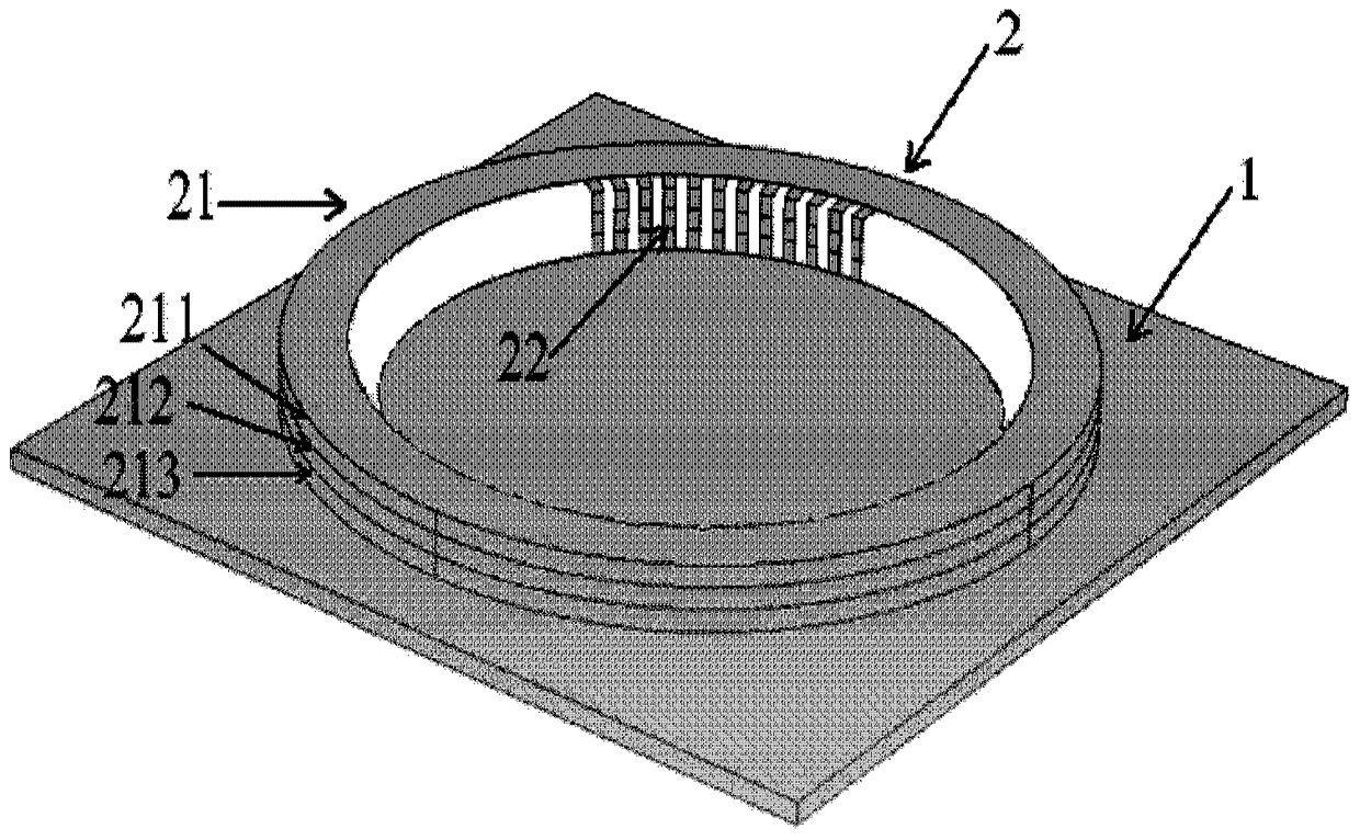
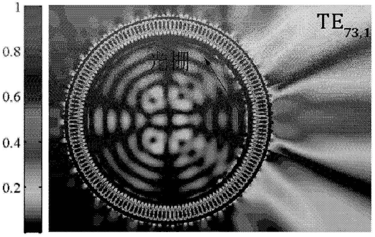
[0030] The ring-shaped semiconductor microcavity laser with grating structure distributed on the inner wall part provided by the present invention controls the far-field output characteristics of different modes in the ring microcavity by selecting different numbers of gratings on the inner wall and the angular period of the grating. The partially distributed grating structure will inhibit the output of light in the area without grating distribution, so that the output of the light field is concentrated in the grating distribution area. Partially distributed gratings couple the WG mode to form a deformed WGM coupling mode containing low-order angular component components, which can realize directional output of the light field. By selec...


PUM


Abstract

The present invention discloses a ring micro-cavity laser with a directional output. The ring micro-cavity laser comprises an annular micro-cavity resonant cavity, and grating structures are etched and distributed on partial inner wall of the annular resonant cavity. The invention provides the annular semiconductor micro-cavity laser, the far field of output light is controlled through the grating structures distributed on the inner wall of a ring part, thus the small-angle single-direction output can be obtained by a high quality factor mode.

Description

technical field [0001] The present invention relates to the field of semiconductor lasers, and in particular to a circular ring microcavity laser with directional output. Directional output of specific patterns can be achieved. By changing the distribution number and angular period of the grating structure, the far-field radiation of the mode can be controlled, so that the mode with a high quality factor can obtain a smaller far-field divergence angle while maintaining a high directional coupling output efficiency. Partially distributed gratings on the inner wall make the annular microcavity laser device realize small-angle directional laser output with high coupling output efficiency through the diffraction regulation of the output light. Background technique [0002] With the rapid development of information technology, the line width of microelectronics technology is gradually approaching the physical limit, and optoelectronic integration has become one of the main goals...

Claims


Application Information

Patent Timeline
Patent Type & Authority Patents(China)
IPC IPC(8): H01S5/10H01S5/06
Inventor 金鑫黄永箴杨跃德肖金龙
Owner INST OF SEMICONDUCTORS - CHINESE ACAD OF SCI
Why Eureka
Try Eureka