Laser fireworks igniter
A technology for igniters and fireworks, which is applied in the directions of fireworks, combustion ignition, weapon types, etc., can solve the problems affecting the promotion and use of fireworks igniters, inconvenient use, etc., and achieves simple structure, strong anti-interference ability, and good unidirectionality. Effect
- Summary
- Abstract
- Description
- Claims
- Application Information
AI Technical Summary
Problems solved by technology
Method used
Image
Examples
Embodiment 1
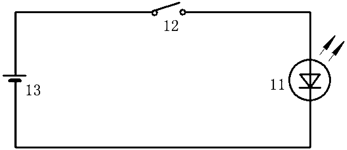
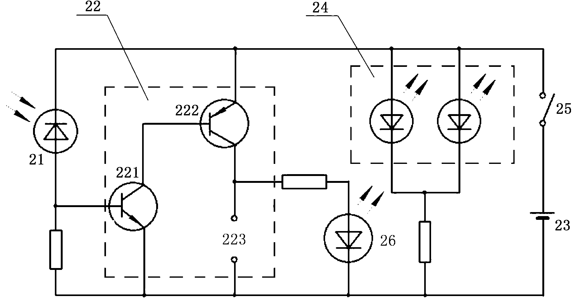
[0028] Such as figure 1 , figure 2 and image 3 As shown, the laser fireworks igniter of this embodiment includes a laser signal transmitting unit 1 and a laser signal receiving unit 2 that cooperate with each other, and the laser signal receiving unit 2 includes an optical signal receiver 21, a receiver power supply 23 and an ignition head 4 for driving Light the output control unit 22 of the fireworks, the optical signal receiver 21 and the receiver power supply 23 are connected in series to form a trigger loop, the output control unit 22 is connected to the trigger loop, and the input end of the output control unit 22 is connected to the optical signal receiver 21 and the receiver Between the power supply 23.
[0029] The laser signal receiving unit 2 also includes a bandpass filter 3 matching the wavelength of the laser signal emitted by the laser signal transmitting unit 1 , and the bandpass filter 3 is arranged between the laser signal transmitting unit 1 and the opt...
Embodiment 2
[0045] Such as Figure 4 As shown, the laser firework igniter of this embodiment is basically the same as that of the first embodiment, and the main difference is that the laser signal receiving unit 2 and the ignition head 4 are integrated, and the laser signal receiving unit 2 and the ignition head 4 are pre-installed on the Inside the firework, the receiving switch 25 is arranged on the outer wall of the firework so as to control the working state of the laser signal receiving unit 2, the optical signal receiver 21 is arranged on the outer wall of the firework so as to receive the laser signal of the optical signal generator 11, and the bandpass filter 3 It is arranged outside the optical signal receiver 21 .
Embodiment 3
[0047] Such as Figure 5 As shown, the laser fireworks igniter of this embodiment is basically the same as that of the first embodiment, and the main difference is that the output control unit 22 includes an NPN type first triode 221, an NPN type The third triode 224 and the PNP type second triode 222, the base of the first triode 221 is the input terminal of the output control unit 22, the base of the first triode 221 is connected with the negative pole of the receiver power supply 23 , the emitter is connected to the base of the third triode 224, and the collector is connected to the positive pole of the receiver power supply 23; the collector of the third triode 224 is connected to the base of the second triode 222, and the emitter is connected to the base of the second triode 222. The negative pole of the receiver power supply 23 is connected; the emitter of the second triode 222 is connected with the positive pole of the receiver power supply 23, and the collector is used...
PUM
 Abstract
Description
Claims
Application Information
 - R&D
- Intellectual Property
- Life Sciences
- Materials
- Tech Scout
- Unparalleled Data Quality
- Higher Quality Content
- 60% Fewer Hallucinations
Browse by: Latest US Patents, China's latest patents, Technical Efficacy Thesaurus, Application Domain, Technology Topic, Popular Technical Reports.
© 2025 PatSnap. All rights reserved.Legal|Privacy policy|Modern Slavery Act Transparency Statement|Sitemap|About US| Contact US: help@patsnap.com


