Supercharge Your Innovation With Domain-Expert AI Agents!

artificial cervical prosthesis

A cervical spine and prosthesis technology, applied in the field of artificial cervical spine prosthesis, can solve the problems of poor adaptability, poor stability of artificial vertebral body, small adjustable range, etc., and achieve the effect of improving adaptability

Active Publication Date: 2017-01-04
SOUTHERN MEDICAL UNIVERSITY
View PDF3 Cites 0 Cited by
  • Summary
  • Abstract
  • Description
  • Claims
  • Application Information

AI Technical Summary

Problems solved by technology

[0006] However, the above-mentioned cervical prostheses can only achieve dynamic fixation after subtotal decompression of a single vertebral body
At the same time, because the individual differences of the human cervical spine are not fully considered, that is, the differences in the height of the human cervical spine between different individuals and different segments of the same individual, the structure of the cervical prosthesis is fixed and the adjustable range is small. Implanting a prosthesis often requires unnecessary trimming of the human cervical spine
In addition, because the angle and height of the pedicle screw are fixed, the screw has poor adaptability to different vertebral bodies during implantation, resulting in poor stability of the artificial vertebral body.

Method used


Image

  • artificial cervical prosthesis
  • artificial cervical prosthesis
  • artificial cervical prosthesis

Examples


example 1

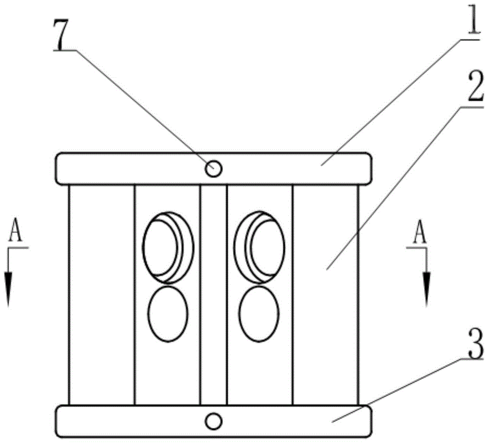
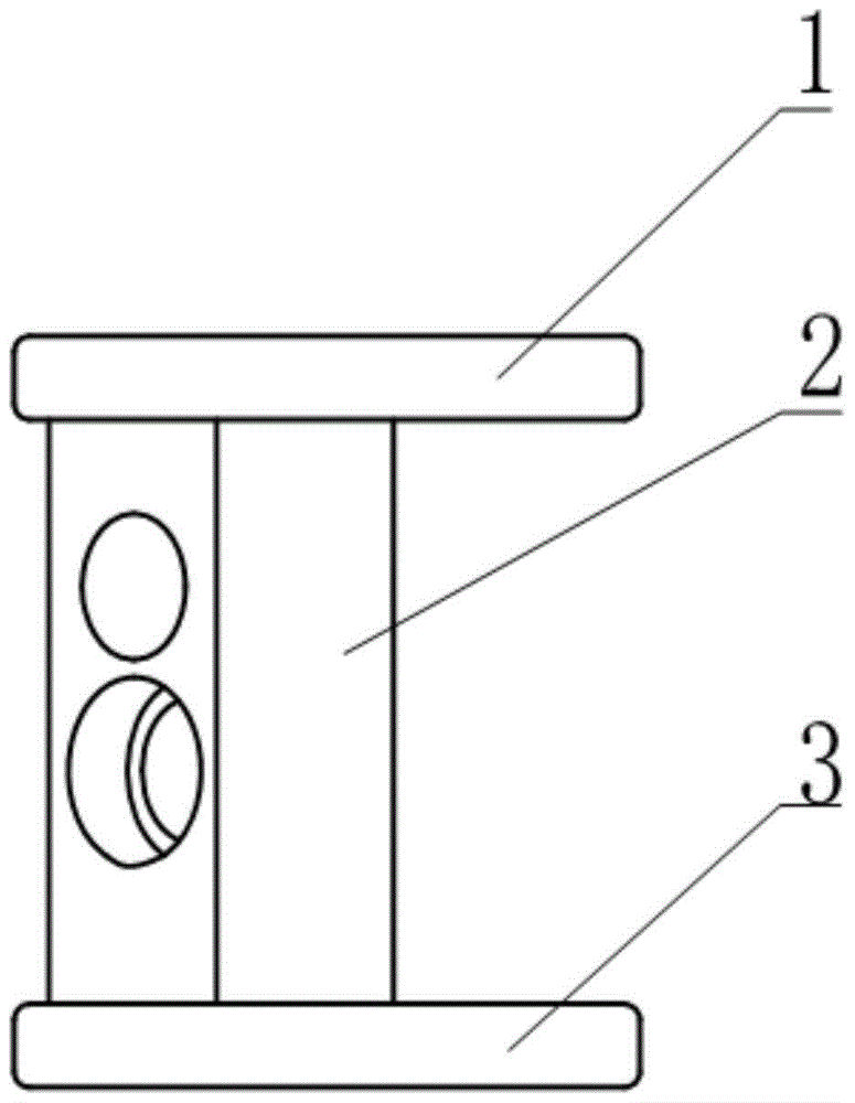
[0026] see Figure 1~5 , The artificial cervical prosthesis in this example includes an upper cover plate 1, a lower cover plate 3, two support columns 2 and four fastening screws 4.

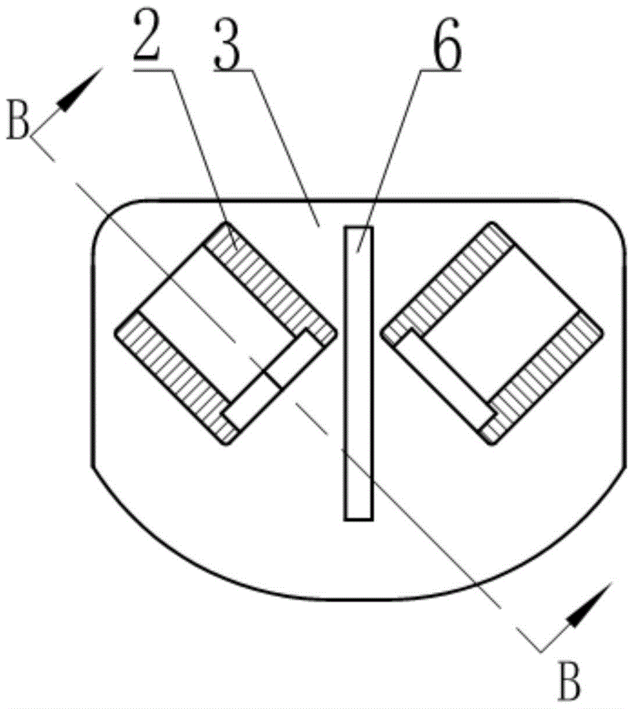
[0027] see Figure 6-8 , the upper cover plate 1 and the lower cover plate 3 are left-right symmetrical structures, and a through groove 6 is provided along the direction of its symmetrical center line, and two counterbores 8 are symmetrically provided on both sides of the through groove 6; the upper cover plate 1 Both the upper surface of the upper surface and the lower surface of the lower cover plate 3 are densely covered with tiny protrusions 5, and a screw hole 7 is provided at the position facing the through groove 6 on the front side of the two.

[0028] see Figures 9 to 11 , the two ends of the support column 2 are respectively provided with coaxial bosses 9 matching the counterbore 8 , and screw holes 10 are provided on the end surfaces of the bosses 9 . The side of the support colu...

example 2

[0034]Since the upper and lower end faces of some intervertebral disc prostheses do not have serrated protrusions, the difference between this example and Example 1 is that the through groove 6 on the upper cover plate 1 and the lower cover plate 3 is omitted, and other structures are the same as Example 1.

[0035] The following combination Figures 14 to 16 Briefly explain the method of dynamic fixation after subtotal corpectomy and decompression of two vertebrae with artificial cervical prosthesis combined with existing Bryan intervertebral disc prosthesis in this case.

[0036] see Figure 15 In this case, combined with the existing Bryan intervertebral disc prosthesis, the dynamic fixation of two adjacent vertebrae after subtotal decompression and decompression was achieved. First, anterior cervical surgery was performed to subtotal resect the middle part of two adjacent diseased vertebrae, and both diseased vertebrae were completely resected. Three adjacent intervertebr...


PUM


Abstract

The invention relates to an artificial cervical vertebra prosthesis. The artificial cervical vertebra prosthesis comprises an upper cover plate, a lower cover plate, two support columns and four fastening screws, the upper cover plate and the lower cover plate are arranged symmetrically, the two support columns and the four fastening screws are sandwiched between two cover plates. Each of the upper cover plate and the lower cover plate is symmetrically provided with two counter bores, each support column is matched with the counter bores through cylindrical bosses at two ends and is fixed tightly through the fastening screws, the side surface of each support column is transversely provided with pedicle screw holes, and pedicle screws passes through the screw holes in the support columns and are connected with a pedicle portion of a corpectomy vertebral body. The artificial cervical vertebra prosthesis is advantaged in that the screw entering angle and the screw entering height of the pedicle screws can be adjusted, and the artificial cervical vertebra prosthesis can adapt to different human body cervical vertebras, the artificial cervical vertebra prosthesis is matched with an existing intervertebral disc prosthesis, and multiple vertebral bodies can be dynamically fixed after the corpectomy.

Description

[0001] Technical field: [0002] The invention relates to a prosthesis for the spine that can be transplanted into the body. The prosthesis is suitable for the subtotal anterior cervical subtotal resection and physiological internal fixation in cooperation with the intervertebral disc prosthesis. [0003] Background technique: [0004] The cervical spine has both stability and mobility, and an ideal cervical spine internal fixation device should have the above characteristics. After surgery, the patient's cervical spine function can be restored, or the original cervical spine function can be preserved as much as possible. Anterior cervical subtotal corpectomy and decompression followed by bone graft fusion is currently the classic surgical method for the treatment of cervical spondylosis. During the operation, the middle part of the diseased vertebra is subtotally resected, and the adjacent intervertebral disc is completely resected. The bone method fuses the diseased vertebra...

Claims


Application Information

Patent Timeline
Patent Type & Authority Patents(China)
IPC IPC(8): A61F2/44
Inventor 张晋元欧阳钧房亚峰孙培栋毕振宇
Owner SOUTHERN MEDICAL UNIVERSITY
Features
  • R&D
  • Intellectual Property
  • Life Sciences
  • Materials
  • Tech Scout
  • Unparalleled Data Quality
  • Higher Quality Content
  • 60% Fewer Hallucinations
Learn More