a composite component
A combination of components, a pair of technology, applied in the direction of building construction, construction, etc., can solve the problems of large gaps in component cross-section shapes, inflexible versatility, and long construction periods, achieving high structural rigidity, saving installation time, and reducing transportation costs. and the effect of installation costs
- Summary
- Abstract
- Description
- Claims
- Application Information
AI Technical Summary
Problems solved by technology
Method used
Image
Examples
Embodiment 1
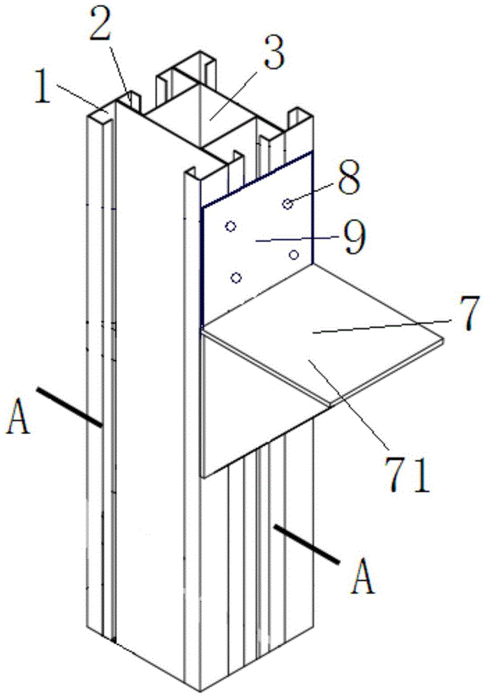
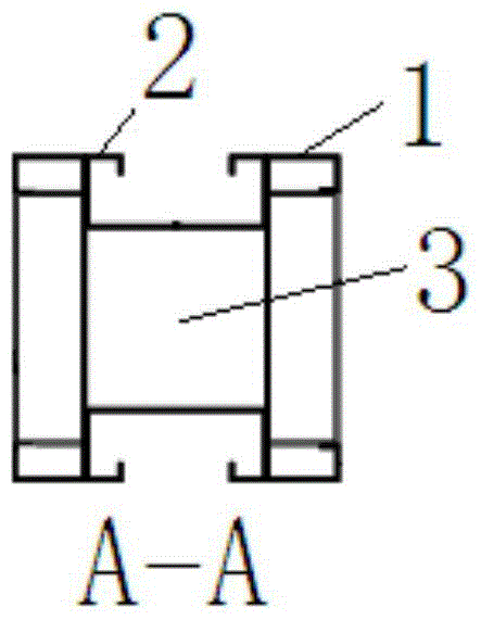
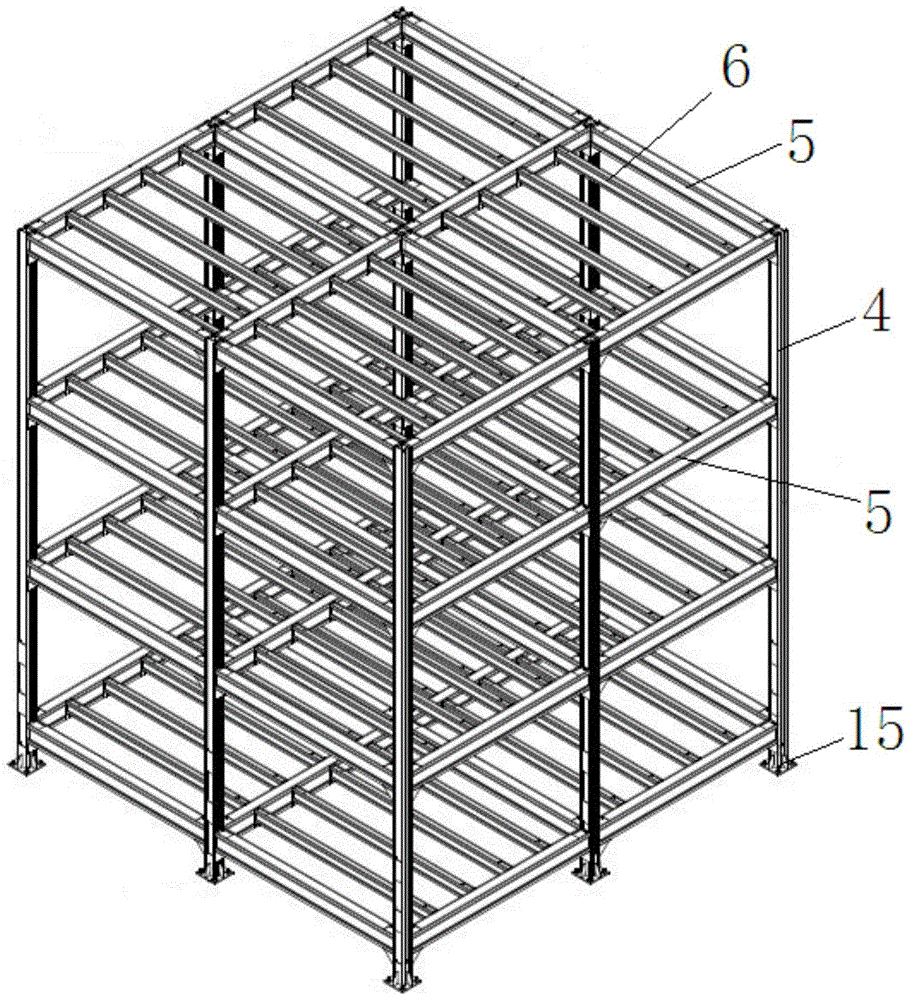
[0025] Such as figure 1 , Figure 4 As shown, when the present invention is used as a column 4 and a main beam 5, several corbels 7 and connecting plates 9 with mounting holes 8 are welded at intervals along the length direction of the section steel on the column 4 and the main beam 5 . The supporting surfaces 71 of the corbels 7 arranged at intervals along the longitudinal direction of the profiled steel on the column 4 are perpendicular to the longitudinal direction of the profiled steel; parallel. Just can distinguish column 4 or girder 5 according to the difference between the support surface 71,72 of corbel 7 and profiled steel length direction like this, if corbel 7 is not set on profiled steel simultaneously, just can judge that this component is secondary beam 6 (as image 3 , Figure 5 shown).
Embodiment 2
[0027] Such as Figure 4 , Figure 5 As shown, when the present invention is used as the main beam 5 or the secondary beam 6, since its two ends need to be connected with two adjacent columns or two main beams, it is necessary to weld the seals with mounting holes 10 at the two ends of the present invention respectively. head board11. At the same time, when the secondary beam 6 is installed on the main beam 5, the secondary beam 6 is located on the supporting surface 72 of the corbel 7, and is fixed through the mounting holes 8, 10 of the connecting plate 9 and the head plate 11 by bolts, so the secondary beam 6 The top of beam 6 will be flush with the top of main beam 5. According to this feature, it can be judged whether the secondary beam 6 is matched with the main beam 5; in addition, it can also be based on the installation of the connecting plate 9 and the head plate 11 on the column 4 and the main beam 5, or between the main beam 5 and the secondary beam 6. The coope...
Embodiment 3
[0029] Such as Figure 6 Shown, when the present invention is used for making multi-storey building, need column 4 lengthening, like this, can weld a plate (not shown in the figure) in the column 4 upper cavity 3 of lower floor, support a set of Pipe 12; Weld the sleeve pipe 12 and the port connection of the lower column 4 cavity 3 into one, and weld a transverse channel steel reinforcement plate 13 at the notches at the ends of the upper and lower columns 4 at the same time. Both the top and the bottom of the steel reinforcing plate 13 are provided with connection holes 14 . When the two columns 4 are lengthened and connected, as long as the cavity 3 at the bottom of the upper column 4 is placed on the casing 12 at the top of the lower column 4 to join the two columns 4, then use each bolt to pass through each of the upper and lower opposite sides in turn. The four connection holes 14 provided on the transverse channel steel reinforcing plate 13 are fixed with nuts; and so o...
PUM
 Abstract
Description
Claims
Application Information
 - R&D
- Intellectual Property
- Life Sciences
- Materials
- Tech Scout
- Unparalleled Data Quality
- Higher Quality Content
- 60% Fewer Hallucinations
Browse by: Latest US Patents, China's latest patents, Technical Efficacy Thesaurus, Application Domain, Technology Topic, Popular Technical Reports.
© 2025 PatSnap. All rights reserved.Legal|Privacy policy|Modern Slavery Act Transparency Statement|Sitemap|About US| Contact US: help@patsnap.com


