Shear pin type bypass valve

A shear pin and bypass valve technology, applied in wellbore/well valve devices, wellbore/well components, earth-moving drilling, etc., can solve the problems of high cost per unit, many sealing parts, complicated debugging experiments, etc. To achieve the effect of convenient entry and exit, avoiding the effect of suction

Active Publication Date: 2015-10-21
BC P INC CHINA NAT PETROLEUM CORP +1
View PDF7 Cites 6 Cited by
  • Summary
  • Abstract
  • Description
  • Claims
  • Application Information

AI Technical Summary

Problems solved by technology

However, the bypass currently in use has a complex structure and cumbersome maintenance and debugging. With the existing equipment, some bypasses cannot realize high-pressure testing for the time being, and due to the complexity of the structure, there are many sealing parts, which are prone to downhole leakage. Different well conditions, Different processes have different requirements for the bypass function, for example, some need to press down and delay, some need to lift up and delay, some need to limit WOB to close, and some need negative pressure lock
In the middle and late stages of oilfield exploration and development, the demand for standard testing techniques is gradually weakening. With the market demand, derivative testing techniques will gradually occupy the testing stage. Due to the high cost of stand-alone maintenance and the complexity of debugging experiments, bypass increases the cost and cost of derivative testing techniques. Labor intensity

Method used


Image

  • Shear pin type bypass valve

Examples


Embodiment Construction

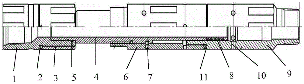
[0013] Below in conjunction with accompanying drawing and specific embodiment the present invention is described in further detail:

[0014] like figure 1 As shown, the shear pin bypass valve of the present invention includes an upper joint 1, a splined mandrel 4, and a lower joint 9. The upper end of the splined mandrel 4 is sleeved with an upper joint 1 through a screw connection, and the splined The lower end of the mandrel 4 is covered with a lower joint 9 that can move up and down along the outer wall of the spline mandrel 4, and an "O" ring 8 is provided on the outer wall of the spline mandrel 4 in contact with the lower joint 9; 4. There is a spline mandrel outer cylinder 6 set on the spline mandrel 4 on the outer side. The upper end of the spline mandrel outer cylinder 6 has a certain distance from the bottom end of the upper joint 1. The lower end of the spline mandrel outer cylinder 6 Screw it on the outside of the lower joint 9 through a screw, and fix it with the ...


PUM


Abstract

The invention discloses a shear pin type bypass valve which comprises an upper connector, a spline mandrel and a lower connector. The upper end of the spline mandrel is sleeved with the upper connector through a screw. The outer side of the spline mandrel is provided with a segment of spline mandrel outer cylinder. A certain distance exists between the upper end of the spline mandrel outer cylinder and the bottom end of the upper connector. The lower end of the spline mandrel outer cylinder is screwed on the outer side of the lower connector through a screw. The spline mandrel outer cylinder is provided with a threaded hole. The outer wall of the corresponding spline mandrel is provided with a mounting groove. The spline mandrel outer cylinder is fixed to the spline mandrel by screwing in shear pins. The side wall, located below the bottom end of the spline mandrel, of the lower connector is provided with bypass holes, so that an inner flow channel of the spline mandrel is communicated with outer bypass annular holes. The outer side of the lower portion of the upper connector is sleeved with a pressing fixing sleeve through screw threads. The outer side of the upper portion of the spline mandrel outer cylinder is provided with an outer screw thread matched with an inner screw thread of the pressing fixing sleeve. The shear pin type bypass valve is simple in structure, the ground pressure test is implemented easily, and the shear pins replace other bypass valves to press downwards and close the bypass valves in a delayed mode.

Description

technical field [0001] The invention relates to a bypass valve for stratum testing operations in the petroleum and natural gas industry, in particular to a shear pin type bypass valve. Background technique [0002] At present, most of the exploration wells and production wells are deviated wells and deep wells. In order to ensure the sealing effect of the packers, RTTS packers are widely used in the oil testing process. However, since the RTTS packer does not have a bypass system, a hydraulic bypass, an openhole bypass or a casing bypass is generally connected to the upper part of the packer to balance the pressure on the upper and lower sides of the packer. However, the bypass currently in use has a complex structure and cumbersome maintenance and debugging. With the existing equipment, some bypasses cannot realize high-pressure testing for the time being, and due to the complexity of the structure, there are many sealing parts, which are prone to downhole leakage. Differen...

Claims


Application Information

Patent Timeline
Patent Type & Authority Applications(China)
IPC IPC(8): E21B34/06
Inventor 贾文义许亚东杨先辉朱礼斌杜成良陈海波于虎基王吉飞张运科
Owner BC P INC CHINA NAT PETROLEUM CORP
Why Eureka
Try Eureka