
Air-conditioning system

An air-conditioning system and solenoid valve technology, applied in air-conditioning systems, heating and ventilation control systems, heating and ventilation safety systems, etc., can solve the problem of poor heating effect of wind-side heat exchangers, impact on service life of air conditioners, and reduced user experience To avoid heat loss, prolong service life and improve heating effect

Inactive Publication Date: 2015-10-21
GD MIDEA HEATING & VENTILATING EQUIP CO LTD +1
View PDF7 Cites 4 Cited by
  • Summary
  • Abstract
  • Description
  • Claims
  • Application Information

AI Technical Summary

Problems solved by technology

[0002] At present, in related technologies, the heating of the air conditioner is realized through the air-side heat exchanger in the air conditioner. However, at this time, the air conditioner usually has the problem of frosting, which has a certain impact on the service life of the air conditioner. Moreover, the heating effect through the air side heat exchanger is relatively poor, which reduces the user experience
In addition, since the used water in the bathroom has a certain amount of heat, it is generally discharged directly from the used water in the bathroom, which causes a waste of energy.
[0003] Therefore, how to use the water that has been used in the bathroom but still has residual heat in the air conditioner, at the same time solve the problem of frosting in the heating mode of the air conditioner, and improve the heating effect of the air conditioner has become a technical problem to be solved urgently

Method used


Image

  • Air-conditioning system

Examples


Embodiment 1

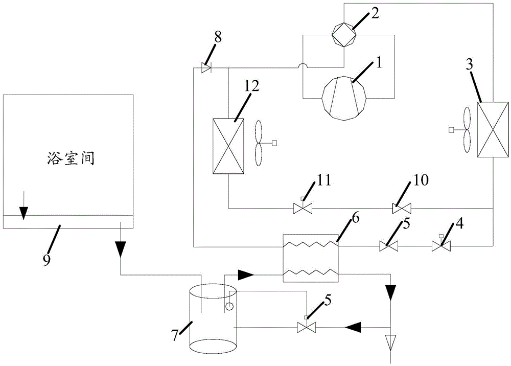
[0049] Such as figure 1 As shown, when the bathroom needs cooling in summer, the air conditioner (air conditioning system) operates in the cooling mode, the second solenoid valve 11 is opened, the first solenoid valve 4 is closed, and the compressor unit 1, the four-way valve 2, and the air side heat exchange The device 12, the second solenoid valve 11, the second throttling device 10, and the indoor heat exchanger 3 constitute a refrigeration cycle system.

Embodiment 2

[0051] Such as figure 1 As shown, when the bathroom needs to be heated in winter, the air conditioner operates in the heating mode, the first solenoid valve 4 is opened, the second solenoid valve 11 is closed, and the compressor unit 1, the four-way valve 2, the indoor heat exchanger 3, The first electromagnetic valve 4, the first throttling device 5, the water side heat exchanger 6, and the one-way valve 8 constitute a heating cycle system, and the waste water in the bathroom (water to be heat exchanged) is treated in the water side heat exchanger 6 By exchanging heat with the refrigerant, the residual heat of the waste water in the bathroom can be fully utilized, and the waste of resources is avoided.


PUM


Abstract

The invention provides an air-conditioning system. The air-conditioning system comprises a compressor unit, a four-way valve, an indoor heat exchanger, a first throttling gear, a water tank and a water side heat exchanger; the compressor unit is formed by one or more compressors; the first end and the second end of the four-way valve are connected to the two ends of the compressor unit respectively; one end of the indoor heat exchanger is connected to the third end of the four-way valve; one end of the first throttling gear is connected to the other end of the indoor heat exchanger; the water tank is used for storing water waiting for heat exchange; and a first inlet of the water side heat exchanger is connected to the other end of the first throttling gear, a second inlet of the water side heat exchanger is connected to an outlet of the water tank, a first outlet of the water side heat exchanger is connected to the fourth end of the four-way valve, and the water side heat exchanger is used for conducting heat exchange between the water, waiting for heat exchange, from the water tank and a refrigerant coming from the indoor heat exchanger. By means of the technical scheme, waste of energy resources is avoided, the problem of frosting caused when the air-conditioning system conducts heating is solved, and meanwhile the heating effect is improved.

Description

technical field [0001] The present invention relates to the technical field of household appliances, in particular to an air conditioning system. Background technique [0002] At present, in related technologies, the heating of the air conditioner is realized through the air-side heat exchanger in the air conditioner. However, at this time, the air conditioner usually has the problem of frosting, which has a certain impact on the service life of the air conditioner. Moreover, the heating effect through the wind-side heat exchanger is relatively poor, which reduces user experience. In addition, because the used water in the bathroom also has a certain amount of heat, generally the used water in the bathroom is directly discharged, which causes a waste of energy. [0003] Therefore, how to use the water that has been used in the bathroom but still has residual heat in the air conditioner, simultaneously solve the problem of frosting in the heating mode of the air conditioner,...

Claims


Application Information

Patent Timeline
Patent Type & Authority Applications(China)
IPC IPC(8): F25B41/04F24F11/00F25B41/20
CPCF24F5/001F24F5/0096F24F11/83F24F11/84F24F2221/18
Inventor 王飞陈得宗王密史作君张宝成
Owner GD MIDEA HEATING & VENTILATING EQUIP CO LTD
Learn More