Multi-lobed soot blower

A soot blower and exhaust gas treatment technology, which is applied in the direction of machines/engines, mechanical equipment, engine components, etc., and can solve problems such as reducing the operating efficiency of exhaust gas treatment components and clogging exhaust gas treatment components

Inactive Publication Date: 2015-10-21
TENNECO AUTOMOTIVE OPERATING CO INC
View PDF7 Cites 10 Cited by
  • Summary
  • Abstract
  • Description
  • Claims
  • Application Information

AI Technical Summary

Problems solved by technology

In this case, the remaining particulate matter and/or soot can build up on other exhaust treatment components, which can

Method used


Image

  • Multi-lobed soot blower
  • Multi-lobed soot blower
  • Multi-lobed soot blower

Examples


Embodiment Construction

[0023] Example embodiments will now be described more fully with reference to the accompanying drawings.

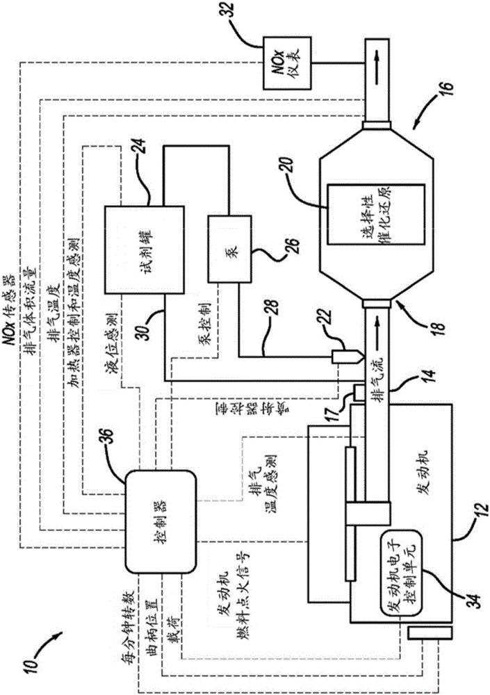
[0024] figure 1 An exhaust system 10 according to the present disclosure is shown schematically. Exhaust system 10 may include at least engine 12 in communication with a fuel source (not shown) that, when consumed, produces exhaust that is discharged into exhaust passage 14 having exhaust aftertreatment system 16 . Downstream of the engine 12 may be located an exhaust treatment component 18 which may be a diesel oxidation catalyst (DOC), a diesel particulate filter (DPF) component, or a selective catalytic reduction (SCR) component 20 as shown. Although not required by this disclosure, exhaust aftertreatment system 16 may also include components such as thermal enhancement devices or burners 17 to increase the temperature of exhaust gases passing through exhaust passage 24 . Increasing the temperature of the exhaust gas facilitates ignition of catalysts in exhaust treat...


PUM


Abstract

An exhaust after-treatment system including at least one exhaust treatment component (18); and a particulate matter dispersion device (40) located upstream of the exhaust treatment component (18). The particulate matter dispersion device (40) includes at least one nozzle line (61) having a plurality of nozzles (58) formed therein, and the particulate matter dispersion device (40) is operable to inject compressed gas towards the exhaust treatment component (18) to substantially minimize build-up of particulate matter at the exhaust treatment component (18).

Description

technical field [0001] The present disclosure relates to engine exhaust aftertreatment systems. Background technique [0002] This section provides background information related to the present disclosure which is not necessarily prior art. [0003] During operation of a diesel engine, particulate matter and / or soot may be generated and passed into the exhaust flow. In order to remove particulate matter and / or soot from the exhaust gas flow, exhaust aftertreatment systems are devised which may comprise so-called Diesel Particulate Filters (DPF). DPFs are designed to filter and remove particulate matter and / or soot from the exhaust stream. However, there are many parts of the world where the use of a DPF may not be required and, therefore, may not be used in the exhaust treatment system in these places. [0004] Nonetheless, even when a DPF is incorporated into an exhaust treatment system, the DPF does not necessarily remove all particulate matter and / or soot from the exha...

Claims


Application Information

Patent Timeline
IPC IPC(8): F01N3/05F01N3/021
CPCF01N3/2066F01N3/2093F01N13/017F01N2610/1453Y02T10/24Y02T10/12F01N3/0233
Inventor 樊高峰杜标王林樊坚强吴安舟吴健迈克尔·戈林
Owner TENNECO AUTOMOTIVE OPERATING CO INC
Why Eureka
Try Eureka