Wing device of flapping machine

A flapping machine and wing technology, which is applied in the field of flapping machine preparation, can solve problems such as a flapping machine wing device that has not been proposed yet, and achieve the effects of good flight effect, easy regulation and low production cost

Inactive Publication Date: 2015-10-28
吴锜
View PDF5 Cites 3 Cited by
  • Summary
  • Abstract
  • Description
  • Claims
  • Application Information

AI Technical Summary

Problems solved by technology

[0002] For a long time, people have dreamed of realizing the technical solution of birds flying in the sky. Many people have imitated the wings of birds and tried to fly, but they have not succeeded; people have conducted long-term analysis and research on the principle of fish parade , mastered some principles of parade, and found that the fish's tail swings from side to side to provide forward power for the parade; because the swinging plane can generate airflow in the vertical direction of the swing, and these airflows can produce a reaction force in the opposite direction, just like We fan fans in our daily life, and the cool wind brought by the fan is not in the direction of the fan surface, but in the vertical direction of the fan swing; there are also wooden boats on rivers, lakes and seas, which rely on the wooden oars on the stern to go back and forth. Swing provides forward motion, which is an example of imitating fish tail swing; At present, many related technical personnel are studying the hydrodynamic principle of fish tail swing to provide power, but in many documents and reports, the fish tail has not yet been proposed. Swing the wing device of the flapper to provide the upward and forward power for the flapper

Method used


Image

  • Wing device of flapping machine

Examples


Embodiment

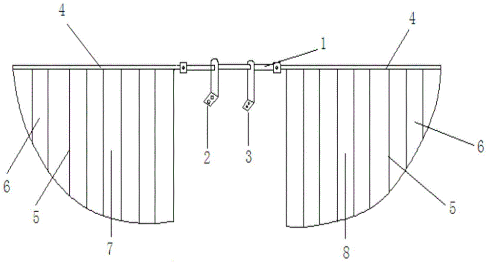
[0011] The main structure of the flapping machine wing device involved in this embodiment includes a connecting shaft 1, a left bracket 2, a right bracket 3, a main frame 4, bones and bones 5, a film 6, a left wing 7 and a right wing 8; it is mechanically connected with the flapping machine power machine A left bracket 2 and a right bracket 3 are fixedly arranged at intervals on the connecting shaft 1, and the left bracket 2 and the right bracket 3 divide the connecting shaft 1 into three parts of equal length, and the connecting shaft 1 passes through the left bracket 2 and the right bracket 3 respectively. The power machine of the battering machine is fixedly connected, and the left bracket 2 and the right bracket 3 support the rotation of the connecting shaft 1; the left wing 7 and the right wing 8 are respectively composed of the main frame 4, the ribs 5 and the film 6, and the left wing 7 of the symmetrical structure and the plane where the right wing 8 and the transverse ...


PUM


Abstract

The invention belongs to the technical field of flatting machine preparing, and particularly relates to a wing device of a flapping machine. A main structure comprises a connecting shaft, a left support, a right support, main frameworks, ribs, films, a left wing and a right wing. The left support and the right support are fixedly arranged on the connecting shaft. The connecting shaft is fixedly connected with a power machine of the flapping machine through the left support and the right support. The left support and the right support support the rotation of the connecting shaft. Each of the left wing and the right wing is formed by connecting and combining the main frameworks, the ribs and the films in a matched manner. The main framework of the left wing and the main framework of the right wing are in mechanical transmission connection with the connecting shaft. The components are matched to form a wing structure of the flapping machine. Climbing force and advancing force are provided for flight through power generated by left-and-right swinging when a fish tail moves, and a flight mechanism of the flight state of the flapping machine is achieved. The wing device is simple in structure, scientific in principle, low in manufacturing cost, easy to regulate, good in flight effect and wide in application prospect.

Description

Technical field: [0001] The invention belongs to the technical field of flapping machine preparation, and in particular relates to a flapping machine wing device, which utilizes the principle of fish tail to design the flapping machine wing structure, and realizes the effect of regulating and controlling the flight state of birds. Background technique: [0002] For a long time, people have dreamed of realizing the technical solution of birds flying in the sky. Many people have imitated the wings of birds and tried to fly, but they have not succeeded; people have conducted long-term analysis and research on the principle of fish parade , mastered some principles of parade, and found that the fish's tail swings from side to side to provide forward power for the parade; because the swinging plane can generate airflow in the vertical direction of the swing, and these airflows can produce a reaction force in the opposite direction, just like We fan fans in our daily life, and the...

Claims


Application Information

Patent Timeline
Patent Type & Authority Applications(China)
IPC IPC(8): B64C33/02
Inventor 吴锜吴开震吴若谷吴若鼎吴若尧
Owner 吴锜
Why Eureka
Try Eureka